Eng-Tips is the largest engineering community on the Internet

Intelligent Work Forums for Engineering Professionals

  • Congratulations waross on being selected by the Tek-Tips community for having the most helpful posts in the forums last week. Way to Go!

Compression controlled reinforced concrete beam Mn determination (simply supported). 3

Status
Not open for further replies.

Future_SE

Structural
Dec 5, 2018
8
0
0
US
I have a bit of confusion when it comes to determining the nominal moment of a simply supported reinforced beam. Personally, I have always stuck to the method of determination being shown in the book (determine the stress in the reinforcement @ concrete failure and plug it into Mn = Asfy(d-a/2)). However, I am currently studying for the PE exam and performing these calculations will be time consuming so I began looking into the PE reference manual for the "simpler method" outlined as shown in the screenshot. You'll note that if you use these methods, you'll get vastly different Mn determinations.

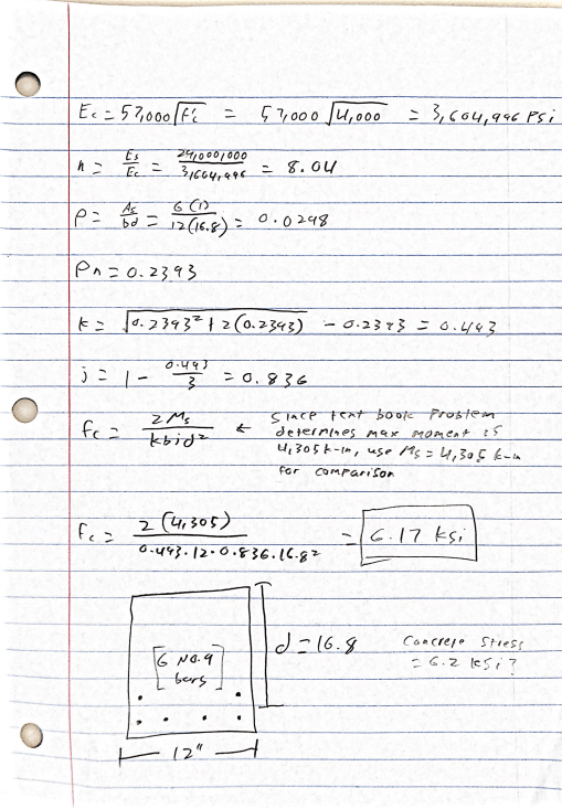
As a check to see if these moments line up, I plugged in the correct Mn shown in the book into and I am getting a concrete stress of 6.17 ksi (when f'c = 4 ksi). So my question is this: why do I get such different values with each method? Should I set the maximum concrete force in the second method to 4 ksi? If this is done, it will result in Mn showing a value of only 2791 k-ft (65% of the value determined in the first method). Thanks for any insights you may be able to provide.

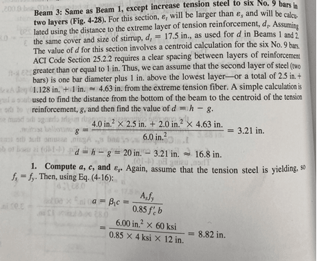
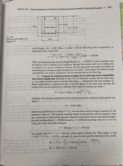
Textbook solution (determination of stress in reinf)

D1_txizqw.png


D2_jgjztm.png


PE Handbook solution
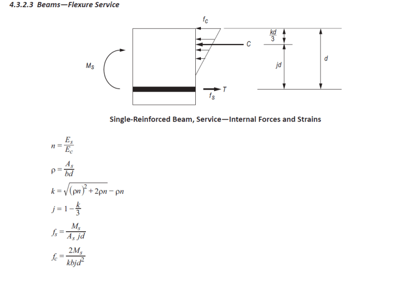
D3_fi8ub8.png


d4_ecysmc.png
 
Replies continue below

Recommended for you

The concrete stress diagram is linear in your figure, which means that it pertains to SLS, not ULS. If you´ve only got one row of rebar, the rest of the equations and parameters (Whitney stress block being the exception) can be deduced from the strain and stress diagrams. If the steel does not yield, Fs = epsion*E*A*((d-c)/c) is the steel stress as shown in the book you cited.

Why do you want to calculate moment capacity for a compression-controlled beam anyway? It results in brittle failure and is thus obviously not recommended (some codes outright ban such designs) by any concrete design code.
 
That might be the piece that I am missing, I appreciate your response. However, I am looking to better understand compression controlled sections in flexure simply to prepare for possible questions on the PE exam. I would never design a reinforced beam that was compression controlled in practice for a list of reasons.

A professor in a PE prep course began using the SLS equations when evaluating a reinforced masonry beam (which utilizes ASD). Does this mean that a linear stress profile should be used for all ASD design? I am still a bit confused as to why a linear profile is assumed for SLS but a stress block is assumed for ULS in the first place.
 
Future_SE:
Review your concrete textbook.

Linear in SLS comes from the assumption that the material remains elastic at service level loading such that the standard My/I or M/s produces accurate stress measurements. At stresses below the rupture stress the full cross-section is considered once you get enough tensile stress to crack the concrete then only the portion of concrete in compression is considered effective with the reinforcing steel.

At the ultimate limit state the actual stress profile is closer to a higher order polynomial up to a critical point and then trails off. The Whitney block is a calibrated simplification of the real stress block to an equivalent rectangular shape giving a resultant compression force and application point at a similar location, and is much simpler than doing a double integral over the compressive stress region for hand calcs.

Some other stress blocks used for ULS:
Capture3_zkjss2.jpg


I'm making a thing: (It's no Kootware and it will probably break but it's alive!)
 
Besides the differing stress profiles (triangular versus rectangular), which centondollar and Celt83 have already mentioned, the two methods you are considering differ in their underlying assumptions.

You are able to determine the stress and strain profiles for the triangular method because it first determines the neutral axis based on the relative stiffness of the concrete and the reinforcing. (That's what the formula for k is doing.) This can only be done for low, service load stresses when the concrete and steel are still behaving linearly.

For the rectangular method, the stresses and strains can be determined because the stress is in the concrete is set to 0.85f'c with a strain of 0.003.

Without these underlying assumptions, you would not be able to determine the stresses and strains because there is an infinite number of magnitudes and depths of the concrete stresses that can result in T = C.

You should be using the rectangular method for determining the concrete capacity even when it is compression controlled. I'm taking a guess that your hold up is in calculating "c" since your book example doesn't show the formula where you can solve for it directly (just use the quadratic equation and then keep that formula ready in your notes). (They instead used an average of forces for T and C which was odd since they should match exactly with the correct "c" value, and they didn't tell you how they came up with "c".)

Structural Engineering Software: Structural Engineering Videos:
 
Status
Not open for further replies.
Back
Top