MegaStructures
Structural
Question not for a current design, just interested.
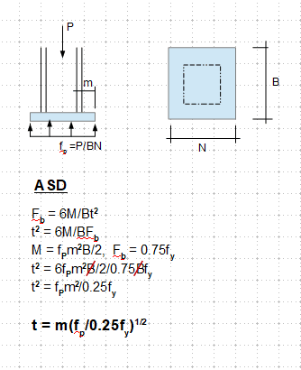
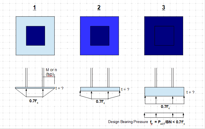
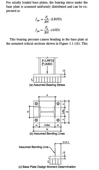
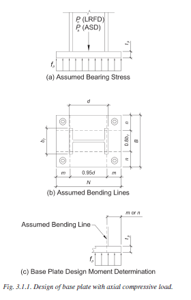
I'm going through AISC DG1 - Base Plate and Anchor Design and noticed that the guide recommends designing the base plate for bending when a compression load is applied to the column. How in the world would a base plate bend from an axial compressive force if it is continuously supported by the concrete underneath it? Is this to account for voids in the concrete? I get that the DG treats the bearing force as uniform across the bottom of the base plate and this force profile would cause "upwards" bending of the base plate if it were able to "travel", but the concrete cannot act on the base plate through a distance.
“Any idiot can build a bridge that stands, but it takes an engineer to build a bridge that barely stands.”
")
![[bigsmile]](/data/assets/smilies/bigsmile.gif "[bigsmile] [bigsmile]")