Continue to Site

Eng-Tips is the largest engineering community on the Internet

Intelligent Work Forums for Engineering Professionals

  • Congratulations KootK on being selected by the Eng-Tips community for having the most helpful posts in the forums last week. Way to Go!

Compressive stress to check in a bearing wall model using finite element

Status
Not open for further replies.

SatoshiNakamoto09

Structural
Sep 2, 2014
25
I am modeling a bearing wall using FE, using STAAD for example and using plate elements, is it correct to use the max absolute stress of an element to compare with the allowable concrete compressive strength? If it isnt, what would it be?
 
Replies continue below

Recommended for you

If the applied loads are un-factored, yes, compare the maximum compressive stress to the allowable stress.
 
If I understand correctly, you have a wall which you modelled with 2d shell elements and you are checking axial stresses in vertical (usually y) direction in each finite element? Did I get this right?

To me, this seems wrong since concrete is not linear (but I haven't really checked in which cases it might be acceptable both from safety and ecenomy). Usually you want to get internal forces and satisfy equilibrium for said forces. Allowable stress approach is useful to get the feel for a structure, but I'd suggest using limit state design for final design.
If your FEM analysis software doesn't give internal forces in 2d elements (just stresses), then you can integrate (in excel easily) the vertical stresses to get the axial force and bending moment and shear "stresses" (usually called n_xy) to get the shear force. Once you have all three internal forces, you can design the wall.

Also, this may lead to nothing useful if for example you're doing seismic design and your wall is ductile (where wall ends are heavily confined where you'd get large strains). In that case it even may lead to wrong conclusions (someone might think "I'll just increase the reduction factor R or behaviour factor to achieve smaller stresses" which would be wrong). Increasing the size of an element in that situation may be counter-productive.
 
Why do it with FEA? Why not on paper? FEA is going to spit out (for starters) a lot of stress concentrations that are pretty much meaningless as far as comparing them to allowable forces (for static analysis and for something like masonry and concrete).
 
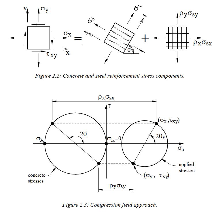
I do not think it is as easy as that unfortunately. The "Practitioners guide to finite element modelling of reinforced concrete structures" [FIB Bulletin 45] gives a method to check the stresses and design the reinforcement based on a compression field approach. But it is not simple.

Capture_tilcms.jpg
 
Finite element software can give unrealistic peak stresses.
 
Owing to technical difficulties, the suggestion to the OP should be focused on the suitability and disadvantages of using FEM for the bearing wall design. In general, FEM should produce results as good as hand calculations, as long as one follows the technical rules, engineering laws, and model the subject correctly. Don't overthink, just run a simple concentrically loaded bearing wall to check yourself.
 
Status
Not open for further replies.

Part and Inventory Search

Sponsor