Continue to Site

Eng-Tips is the largest engineering community on the Internet

Intelligent Work Forums for Engineering Professionals

  • Congratulations KootK on being selected by the Eng-Tips community for having the most helpful posts in the forums last week. Way to Go!

Computing Axial Unity for a Reinforced Concrete Column with axial load and biaxial moments

Status
Not open for further replies.

jochav52802

Structural
Nov 28, 2018
81
Good Afternoon,

I'm working on a project in a high-seismic zone with cantilevered columns, and per ASCE 7-16, am required to keep the axial unity for seismic load combinations to 15% or below.

I'd appreciate any guidance on how what process I might follow to verify this.

Generally, it seems that 3D interaction diagrams are used to show where the applied moments sit relative to the available moment capacity at the applied axial load. Since this information is based on taking a slice through the 3D interaction diagram at a specific applied axial load, I'm not sure how to come up with an axial capacity given the applied moments in order to compute the axial utilization ratio.

Any insight is appreciated; it's been awhile since I've had to design a concrete column :)

Thank you!
 
Replies continue below

Recommended for you

The program and spreadsheets we use generate the P-M diagram based off the capacities regardless of applied loads. Then you plot your applied loads against it to make sure it is within the envelope.

If it's asking about axial capacity only, couldn't you determine the allowable axial load at the applied moments and then check that allowable axial load against your applied axial load to check utilization?
 
This is a tough thing to do by hand. I suggest getting a license for SPcolumn if you'll be doing a lot of this.
The simple answer though is that you have to produce a diagram at each of your axial loads for confirmation of suitable corresponding moment capacity.
 
Aside from software.....most concrete texts have interaction diagrams where (based on shape, percentage of reinforcement, cover, etc) you can come up with allowable axial force and so on. Jack McCormac's 'Design of Reinforced Concrete' (3rd ed) has such tables (see p. 667-672). Allan Williams's 'Structural Engineering Reference Manual' does as well.
 
Thanks jayrod12, I think your method is the path forward I'm after. Although it's a little painful even with SPColumn since it doesn't appear that SPColumn allows you to determine what the corresponding axial capacity is for an applied moment, (it seems to just allow you to hover over their graphs and approximately project up to the design envelope to determine the corresponding axial capacity.) I think it'd be a nice upgrade to that program if it allowed you to input a moment and output at that applied moment what the available axial capacity is. Maybe that's already possible and I just don't know how to use it, (if anyone has any helpful insight, it's appreciated!)

Thanks atrizzy, so the method you're describing is easy in SPColumn, however, I'm trying to determine the column's axial capacity based on the applied moments, so that I can determine the axial unity ratio in order to confirm that it's 15% over lower. Thanks for weighing in.

Thanks WARose, I think SPColumn does a really good job of covering cases that the texts may not cover, with relatively little input effort.

 
Thanks WARose, I think SPColumn does a really good job of covering cases that the texts may not cover, with relatively little input effort.

Yeah, if you got software....have at it. But if your resources are limited as far as software goes.....all sorts of manual methods are out there. (I.e. Bresler's equations, the PCA Load Contour Method, etc, etc. PCA's 'Notes on ACI 318' is another good source for all this.)

 
Thank you WARose, excellent point and suggestions!
 
If I understand what your looking to get then a supplementary VBA routine on top of IDS’s spreadsheet is what you may end up needing.

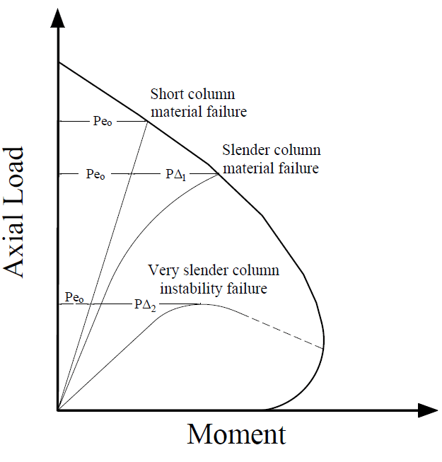
If your column is non-slender then you can take your load point and project it vertically to the failure surface to get the Axial unity assuming no change in moment.

If your column is slender then you’ll need to iteratively step the axial load and perform moment magnification procedures until your failure line either reaches the failure surface or reaches Pcrit.

89FD5682-9CC0-43A3-BF0F-520D8C5958E0_fwuwye.png


My Personal Open Source Structural Applications:

Open Source Structural GitHub Group:
 
Thank you ProgrammingPE,

That's a great idea, and I can't see how it won't work.

It does require a little manipulation; I'll extract the loads from RISA-3D to a spreadsheet, factor the axial loads by 6.67 times and insert it along with the unmodified moments into SPColumn to confirm that the resulting points all fall within the 3D interaction design diagram.

Thanks again!
 
Status
Not open for further replies.

Part and Inventory Search

Sponsor