Continue to Site

Eng-Tips is the largest engineering community on the Internet

Intelligent Work Forums for Engineering Professionals

  • Congratulations waross on being selected by the Eng-Tips community for having the most helpful posts in the forums last week. Way to Go!

Concentric holes - shifting datum MMC or LMC?

Status
Not open for further replies.

Th.Ro.

Mechanical
Apr 2, 2019
23
Problem:
2 concentric holes that need to maintain a minimum distance between their walls.

If the larger hole, which provides the reference datum, is at its maximum tolerance the smaller hole can be more off its ideal position - see large view in below image.

Which would be the correct drawing call-out for the datum shift, the upper one with MMC for the datum or the lower one with LMC for the datum?
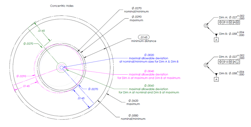
Capture_kkydfh.png
 
Replies continue below

Recommended for you

I think we all agree on the x minimum in both cases (position Ø zero at LMC |A| and position Ø zero LMC |A(M)|) as being 0.0145.

Now, speaking about X maximum we do not have such agreement.
I have to admit that I recalculate X maximum and I got .0205 in BOTH cases (instead of .0195 has I calculated few days ago).
I still do not understand why there is a difference between those cases regarding X maximum value.

Since I do not want to have any misunderstandings on what X maximum means I would say it is the maximum possible distance that can ever happen in a single cross section for cases: position Ø zero at LMC |A| and position Ø zero LMC |A(M)| cases.

As far as my calculations go: X maximum: .058/2 +.004 (form error on datum feature A) -.027/2 +.002/2 = .0205

I do not see any difference in the applicability of this math regarding those two cases: position Ø zero at LMC |A| and position Ø zero LMC |A(M)| cases.
I get the same number/ value of both

I am not sure how Burunduk end up with his numbers, even with his explanation there. I also understand that Burunduk and SeasonLee got the same X maximum value, but I am not sure I agree with them both. Sorry.

Again, I agree with Burunduk's .0205 value for position Ø zero at LMC |A(M)| case, but not with .0185 value for position Ø zero LMC |A| case.

Anyone else like to do a "simple" math to correct me where I am wrong.


I think this case is incorrect:
"Maximum wall distance calculation for the LMC/RMB case:
Max. Wall Distance = A + y
Where:
A = Max. distance from datum hole A surface to LMC boundary of the smaller hole.
y = Max. distance from LMC boundary of the smaller hole to surface of the smaller hole.
A = (largest datum hole dia.* - LMC of smaller hole)/2 = (.062 -.058 - .029)/2 = .0165.0145
(* Note: The LMC boundary is centered to the UAME of the datum hole. Any form variation of datum hole A will make the UAME smaller than the largest actual local size but it will not influence distance A. No actual local size may be larger than .062 therefore .062 diameter is used for the calculation.)
y = .029 - .027 = .002
Max. Wall Distance = A + y = .0165.0145 + .002 +.004 (form error on datum feature A) = .0185"
= .0205

Disclaimer: in the case of X maximum being the maximum possible distance that can ever happen in a single cross section.

The maximum distance is happening when datum feature A is at its MMC and has all its form error located in only one spot or so called the form error has a "bump". In the case the datum axis would be at the center of mostly .058 diameter.
 
Season Lee, your calculation is correct too. It is based on the axis interpretation, this is why you mention the bonus tolerance.
My calculation was done with the surface interpretation in mind. In my description too, the datum hole is produced at its largest size - .062, and the considered hole was produced at its smallest size- .027. The datum feature simulator for the RMB case matches the size of the datum hole, and coaxially to that datum feature simulator, there is the virtual condition boundary of the smaller hole, equal in size to its LMC (actually, wherever I mentioned LMC in the calculation description I should have used the term resultant condition to make the description correct not only for this specific case). The maximum wall distance occurs in the following condition: The smallest size considered hole translates in some direction as much as the virtual condition (of LMC size boundary) allows. Therefore the maximum wall distance is the radial distance between the surface of the datum hole (of size .062) and the VC (of LMC size, .029), plus the maximum distance between the VC boundary and the surface of the considered hole of smallest size: which equals 0.29-0.27=.002.
Hence Max. Wall distance = (.062-.029)/2 + 0.02=.0185.

Let me know if it's clear or not.
 
greenimi, I hope the above latest description of the RMB/LMC case will clarify things for you. Just sketch it and you will see. Form error of datum feature A is irrelevant to the calculation because as I explained it does not enlarge the maximum wall distance. The form error will only mean that the UAME/datum feature simulator/true geometric counterpart of datum hole A is smaller than .062, but even at that condition, the maximum wall distance can be the same as in the case of perfect form datum feature A at the largest size.
 
Burunduk said:
Form error of datum feature A is irrelevant to the calculation because as I explained it does not enlarge the maximum wall distance. The form error will only mean that the UAME/datum feature simulator/true geometric counterpart of datum hole A is smaller than .062, but even at that condition, the maximum wall distance can be the same as in the case of perfect form datum feature A at the largest size.

I am still not convinced.
Reason (as I stated above): The maximum distance is happening when datum feature A is at its MMC and has all its form error located in only one spot or so called the form error has a "bump". In the case the datum axis would be at the center of mostly .058 diameter. An increased in the maximum condition can occur in this case hence .0185 is incorrect and .0205 is the correct value.

Anyone else?

 
I haven't read every post carefully, but this could be an issue of "maximum wall thickness at one spot" vs. "maximum consistent wall thickness."
 
Belanger said:
I haven't read every post carefully, but this could be an issue of "maximum wall thickness at one spot" vs. "maximum consistent wall thickness."

J-P,
I already have my disclaimer very clear (I hope)
Disclaimer: in the case of X maximum being = the maximum possible distance that can ever happen in a single cross section.
 
greenimi, SeasonLee
Here is another way to arrive at the same numbers, using acceptable terms and concepts from Y14.5:

Consider that:

LMCA = least material condition size of datum feature A (largest hole).

DS = datum shift

RC = resultant condition of the smaller hole

The general formula is:
Maximum Wall Distance = (LMCA + DS - RC)/2

In the RMB/LMC case:

LMCA=.062
DS=0 (because A is specified RMB)
RC=.027-.002=.025

Maximum Wall Distance = (LMCA + DS - RC)= (.062 + 0 - .025)/2 = .0185

In the MMB/LMC case:

LMCA=.062
DS=.004
RC=.027-.002=.025

Maximum Wall Distance = (LMCA + DS - RC)= (.062 + 0.004 - .025)/2 = .0205

I'm still not sure regarding the effect of form error, but If form error for datum feature A should be added, it should be added in BOTH "maximum distance": cases, because in both cases datum feature A is considered to be produced at LMC size and allowed the maximum rule #1 form error in that condition.

greenimi, since you think that the maximum distance should be the same for both cases, does it mean that in your opinion the datum shift has no effect?

Also of note:
Experts may not like the fact that we are trying to determine the wall distance here because unlike with the usual examples of "wall thickness" calculation there is no direct distance "in single cross section" between two coaxial holes. It is a distance between two offset surfaces and can only be determined as a projected distance from two different locations (along the axial direction) to a single plane. There may be some ambiguity with how exactly such distance is supposed to be determined.
However, this is the kind of wall distance the OP is investigating (though the question only dealt with maintaining a minimum value of wall distance).
 
Burunduk said:
I'm still not sure regarding the effect of form error, but If form error for datum feature A should be added, it should be added in BOTH "maximum distance": cases, because in both cases datum feature A is considered to be produced at LMC size and allowed the maximum rule #1 form error in that condition.

greenimi, since you think that the maximum distance should be the same for both cases, does it mean that in your opinion the datum shift has no effect?

I think you can apply either datum shift (if available from MMB) either form error but not both.

Therefore, since in the LMC/MMB case you already applied datum shift then no form error for the datum feature is again to be applied (hence .0205 value).
Now speaking about LMC/RMB case, there is no datum shift available and then consequently the form error should be applied (again because I explained before about the form error "bump") so, consequently in this case you are missing the form error and instead you got only .0185. If you consider the form error you will get the same value .0205 as the previous case.

Again, this is my opinion. If I am wrong then I will stand corrected, as I stated before.

I am also fully aware about the addition I have added to the original question posted by the OP. (maximum value was not requested by the OP but by me). I hope the OP does not mind. I am doing it to learn the correct way to do this kind of "simple" stackup calculations. Looks like they are not so simple even they have only two features involved...…
 
greenimi said:
I think you can apply either datum shift (if available from MMB) either form error but not both.

Why can't the same "bump" you were talking about occur on a datum feature that shifts?
 
I think I see what you are getting at - datum feature A has to be of perfect form to utilize the entire maximum possible datum shift. Is that correct?
 
Burunduk said:
datum feature A has to be of perfect form to utilize the entire maximum possible datum shift.

Yes, I think you are correct here.
Rule#1 is applicable to A so if you apply form error and datum shift you will violate the limits of size .058-.062 , don't you?
Reverse rule#1 -perfect form at LMC -is applicable only to .027-.029 hole.

So do you agree that .0205 is the "new" value (X maximum ) regardless if A is RMB or A is MMB?


greenimi said:
So do you agree that .0205 is the "new" value (X maximum ) regardless if A is RMB or A is MMB?

At this point, I think I do, although it seems odd that the MMB modifier and the datum shift it permits don't provide an allowance for additional relative displacement between the datum feature and the considered feature. We know that the minimum distance is the same but that makes sense because this what the LMC virtual condition for the small hole and the MMB boundary for datum hole A (in the MMB case) or perfect form at MMC for datum hole A (at the RMB case) ensures. It is surprising that MMB doesn't add more permissible mutual dislocation to enlarge the maximum distance.

I can see how this happens but something about it contradicts my understanding of the effect of datum reference at MMB.
Can you add some more insight to rationalize this?
 
Burunduk said:
I can see how this happens but something about it contradicts my understanding of the effect of datum reference at MMB.
Can you add some more insight to rationalize this?


Study this discussion:

and specially the post from pmarc
pmarc said:
pmarc (Mechanical)
13 Dec 12 16:02
Well, first of all I think we should finally tell the others which textbook we are discussing about - just to have more votes in further discussion. It is "Fundamentals of GD&T (2nd Edition)" by Alex Krulikowski.

Knowing that, in my opinion calculations shown in figure 9-13 are OK. In this case, if we want to have maximum datum feature shift, datum feature hole must be at 10.4 and perfectly perpendicular to A. Each other configuration of the hole will give datum feature shift smaller than 0.4, however on the other hand...

...there is another interesting aspect. If, just for the purpose of excercise, we delete (M) modifer standing right after 0.2 in positional feature control frame for the smaller hole in 9-13, so that the bonus tolerance is not available, we should get 2.7 (at least this is what I get). Which leads to a conclusion that according to what I keep claiming about figure 9-12 (so that the correct answer shall be 2.7, and not 2.9), there is no difference whether datum B reference in positional callout is modified by (M) or not. Minimum wall thickness will always be 2.7. Hmmmm...

Does someone see my point?
 
Status
Not open for further replies.

Part and Inventory Search

Sponsor