Continue to Site

Eng-Tips is the largest engineering community on the Internet

Intelligent Work Forums for Engineering Professionals

  • Congratulations SSS148 on being selected by the Eng-Tips community for having the most helpful posts in the forums last week. Way to Go!

Concrete Balcony Thermal Breaks

Status
Not open for further replies.

bookowski

Structural
Aug 29, 2010
983
Two questions for anyone who uses thermal breaks at concrete balconies, in particular I'm talking about isokorb. I've read the technical literature but just looking for any input/warnings from people that use them on the following:

1. The add'l deflection from the thermal break in my case adds about 1/2" deflection at the top of balcony. I am very hesitant to camber a balcony - afraid they'll do too much, it won't come down as much as it 'should' etc. and I create a drainage problem.

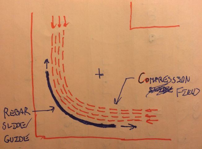
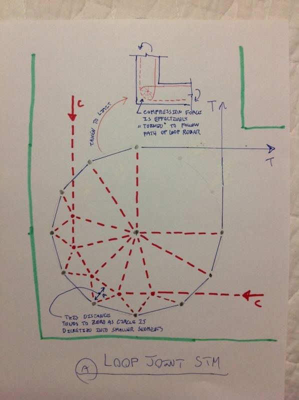
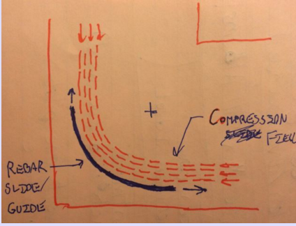
2. Has anyone used the thermal break for step down balconies, in particular the isokorb k-hv10-cv35. To deal with the step down the included reinforcing does a 360 loop to go from low to high. Seems a bit scary. Anyone use this?
 
Replies continue below

Recommended for you

bookowski said:
but who wants to deal with calculating B.

To clarify, it definitely wasn't my intent to suggest that you or anyone else ought to be calculating B. I was merely proposing the concept to support our mutual concern regarding whether or not balcony camber would come out. The double counting of "B" is just one factor that might contribute to an overly conservative estimate of total deflection.

bookowski said:
Seems like the mechanism is that the hoop is like wrapping a cord around a gear, the concrete becomes a confined wheel which 'turns' the force around the corner.

Quite. The fact that the gear turns the rebar tension probably wasn't much of a surprise to anyone. For me, the revelation was that the same gear might also turn the concrete compression. In the limit, I've come to think of the lower left quarter of the hoop as something similar to a water slide with water poured in vertically at the top and shot out horizontally at the bottom. I'd very much like to see an FEM study of one of these joints.

Capture_chox2i.jpg


I like to debate structural engineering theory -- a lot. If I challenge you on something, know that I'm doing so because I respect your opinion enough to either change it or adopt it.
 
Looks fun. But the bar in tension is in contact with and parallel to the compression?
 
This opening corner detail should get its own post. It would be good service to the community to collect all of our discussions and references in one location.

@KootK - A couple things about your STM -
Moment compatibility tells us that the resultant compression strut will cross the diagonal at a little more than 1/2 the diagonal length - any tension in the back end of the loop reinforcement will require a significantly higher compression strut.
strain compatibility requires the tension and compression elements not be next to, or in line with each other. I understand it can be used to simplify the model but the back end of the loop will either be in compression or very little tension.
The biggest problem with an open corner STM is that the compression strut will be either completely outside or mostly outside the reinforcement envelope and we need to institute a dummy tension tie to pull the compression strut in at the corner.
Here is another resource regarding recent testing done to an open corner detail with 3 different reinforcing details - of note, the results and recommendations are a bit counterintuitive. The proposed STM for the report shows up on the last page.


- edit - tried to fix diagonal load value in corner detail - it should be root 2 x T
 
First off, I'm just having fun here pitching a possible theory to explain the mechanics of the loop joints. I find it an interesting problem to study because, as far as I can tell, nobody else has proposed a competing theory. No one should be taking all this stuff too seriously

bookowski said:
But the bar in tension is in contact with and parallel to the compression?

teguci said:
strain compatibility requires the tension and compression elements not be next to, or in line with each other.

teguci said:
The biggest problem with an open corner STM is that the compression strut will be either completely outside or mostly outside the reinforcement envelope and we need to institute a dummy tension tie to pull the compression strut in at the corner.

Yeah, there's that. That's what actually led me to the wacky STM model. The way I see it, you've got three choices for how you could take the compression force around the outside of the corner rather than diagonally across it.

1) The concrete compression rounds the corner slightly to the inside of the rebar. Concrete only in compression (STM above).

2) The concrete compression rounds the corner slightly to the outside of the rebar. Minor reliance on concrete in tension.

3) The concrete compression rounds the corner right over top of the rebar. You have strain compatibility issues but I believe that this is still a physical possibility. In a way, every piece of rebar that was ever developed / anchored within concrete is an example of this: tension strained rebar existing within a nearly parallel concrete compression field.

While the compression strut being right on top of the tension rebar gives me a headache, the strut being in close proximity to the bar really does not. Once a viable STM is established, I think that it is just a matter of scale. If this joint were ten feet across rather than eight inches, strain compatibility issues would be much more innocuous.

Teguci said:
Moment compatibility tells us that the resultant compression strut will cross the diagonal at a little more than 1/2 the diagonal length...The proposed STM for the report shows up on the last page

That's the whole point of the STM exercise really. When the crappy corner details are used, you do do get that diagonal strut and your effective member depth becomes seriously compromised (STM model below from the excellent doc that you posted). Testing has made it abundantly clear that the looped joints perform much better than the lesser details. The question that I'm trying to address is why. With my STM model, I'm proposing that the the reinforcing loop allows the concrete compression strut to hug the outside of the corner more closely. And that would result in an improved flexural depth across the corner.

Capture_xu2kgw.jpg


I like to debate structural engineering theory -- a lot. If I challenge you on something, know that I'm doing so because I respect your opinion enough to either change it or adopt it.
 
I'm not taking it too seriously. The real question of this post is:
- would you use this
- assuming camber is off the table how do you live with/deal with the extra .5" to .75" deflection
- and the real hope was anyone that has done this a few times and has some input on do/don't do this when you use one of these
 
I kinda figured that the original question had run its course and that it was safe to dabble in other areas of interest as you and I have often done in the past. It's sounds as though that is not the case so I shall cease and desist with tangential stuff.

I like to debate structural engineering theory -- a lot. If I challenge you on something, know that I'm doing so because I respect your opinion enough to either change it or adopt it.
 
The hoop tangent is very interesting. When I speak to isokorb I'll see if the germans have any insight.

Just also trying to figure out if I'm the canary in the coal mine with using that detail.
 
I don't have anything to add about the insulated joint, although I find it weird.

But as to the loop around the opening joint, I think it does essentially the same thing as two hairpins, which is the accepted way of creating efficient opening joints. We discussed this in another thread recently.
 
Sooo... I was surfing the net for STM models on a Friday afternoon because, now that I'm married, that's what passes for porn. Low and behold, I stumbled across the first diagram below for an STM explaining a hooped opening joint. Look familiar? Like somebody's nutty wagon wheel STM from the not too distant past? Oh yeah it does...

The model comes from here: Link. I have no idea who these "TransTutor" folk are or whether they ought to be trusted but, at minimum, someone other than me has been thinking this particular thought.

Capture_bzplzj.png

Capture1_hvlkhs.jpg

Capture3_wao2vv.png


I like to debate structural engineering theory -- a lot. If I challenge you on something, know that I'm doing so because I respect your opinion enough to either change it or adopt it.
 
Status
Not open for further replies.

Part and Inventory Search

Sponsor