Continue to Site

Eng-Tips is the largest engineering community on the Internet

Intelligent Work Forums for Engineering Professionals

  • Congratulations waross on being selected by the Eng-Tips community for having the most helpful posts in the forums last week. Way to Go!

Concrete breakout resistance of anchor in tension

Status
Not open for further replies.

Dam lover 68

Structural
Sep 5, 2024
2
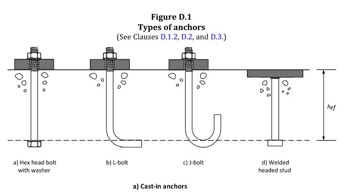
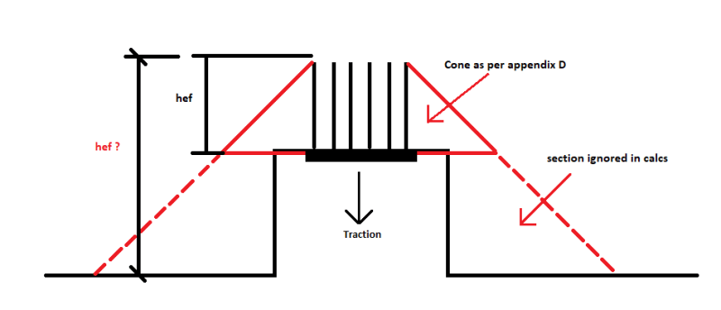
I have an unusual design to validate and was looking for some opinions on what can be considered as the usable area for concrete breakout in tension. In the situation where the anchors would be inside a reservation in the concrete would it be possible to consider a bigger breakout cone?


If the anchors are below the surface of the breakout "cone" could the top of concrete be considered for hef? Meaning top of concrete to bottom of anchors instead of top of anchors to bottom of anchors.
thumbnail_image_kkeqyg.png


Capture_z62cxu.jpg

I am looking for some input as to why this would or would not be a thing.

Thanks
 
Replies continue below

Recommended for you

Obviously the safe play is to discount the proposed hef and use the "cone as per appendix D" but i'm assuming doing that is not favorable which is why you are asking about it. If this a design or analysis? If design, I could probably get comfortable with engaging that greater cone by placing some bars along side the anchors or in such a manner as to ensure that the overall cone performs as one and reinforces that plane of weakness at the surface of your anchors.

And by the way, if you are using Appendix D you are a couple of ACI 318 versions behind.
 
Sorry forgot to mention that this is an analysis for new loads on an existing anchor group in mass concrete. I also forgot to mention that this is for CSA A23.3-19 as I am in Canada, so Appendix D is the norm here for anchor design. The concrete is also confined in steel plating.

Thanks
 
I would give you a solid 'it depends'. If the cutout is small compared to the breakout cone I'd say you could probably ignore it. I don't know what 'small' means exactly, though.

Your problem is going to be looking for mechanisms that aren't normally checked for because they inherently won't govern in normal construction that may end up governing here.

There are a few problems.

You may potentially need to resolve tension along the face of the inset piece where the anchor plate is if the full cone is taken as bridging between two support points.

Do you have enough space within the cone boundaries to pass your force? Can you dimensionally fit a strut, for instance, in the most confined point.

In parallel with the last one but from a different model of concrete, is there a shear breakout mechanism that is higher energy than the normal one in most cases but could happen here. i.e. what happens as the angle of the potential failure plane gets steeper so it intersects with the less deep portion. It gets harder to break but it still isn't full compression bearing capacity (for instance, the enhanced shear provisions as you approach supports in some codes would presumably be a similar thought process). Same thing where whether this is important will depend on your various dimensions. There's some point where it's obvious that it can't breakout and there's only a potential pullout.

Your partial cone zone each side of that hole is two half triangles that are unconfined on one side. Draw a free-body diagram of that and think about it for a while. It's going to want to rotate. If the hole is small then you'll get some pretty good support in the third dimension, but it depends.

The pullout mechanism is definitely the smaller height and might govern even if you justify breakout somehow.

edit: what your reinforcement looks like is going to make a reasonable difference.
 
Status
Not open for further replies.

Part and Inventory Search

Sponsor