Eng-Tips is the largest engineering community on the Internet

Intelligent Work Forums for Engineering Professionals

Concrete "C" Shaped wall design - unbraced height 3

strguy11

Structural
Nov 29, 2005
229
0
0
US
I have a project with "c" shaped concrete core walls for both shear and gravity.

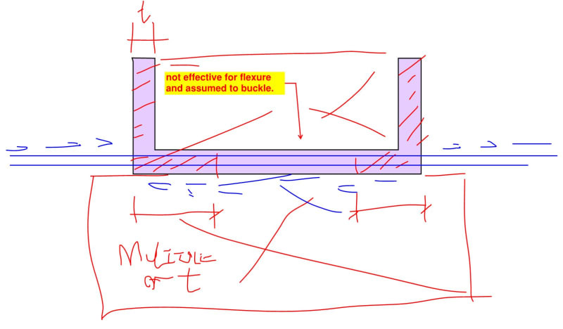
The walls surround an elevator core, so on the "inside" of the "c" shape, there is no floor. On the other side of the web, there is a stair opening, so the web of the wall group is technically unbraced for 5 stories. There is always a floor on the outside portion of the flanges, so those are braced.

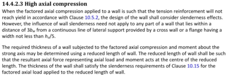
My question is when designing these as a group, can you still consider the unbraced length for axial load as the floor to floor, since the flanges are braced? I cant find any design guidance on this topic.
 
Replies continue below

Recommended for you

My opinion is that the unbraced length for overall buckling should be taken as the story height. I can't visualize the web-wall first-mode buckling shape over a distance of 5 stories. It would have to tear off along the flange-wall junctions, since those walls are laterally supported at each story. In other words, whatever the flange-wall buckling shape is, the web wall will follow suit. Again, just my opinion, but I believe this is would be the buckling response based on deformation compatibility within the overall C-shape section (i.e., plane sections remain plane).
 
Or would you use the length of the wall as the buckling height due to the restraint provided by the flanges? That's more where I'd be inclined. Or maybe the larger of, length of wall versus storey height.
 
I hate that condition and had to deal with it recently. In addition to the wall buckling thing, it can be tough to get the shear into the rear wall of the shaft. With no slab on either side, you pretty much have to drag it in directly through a discrete rebar drag strut in the wall rather than slab / wall shear friction. That can be a problem when you're talking large numbers.

How to deal with the buckling seems to be a moving target from a code perspective. In the past, I've used h/20 or h/15 slenderness limit turned sideways rather than considered vertically. I've seen this done in references and it makes some sense to me.

Recent versions of Canada's concrete code now direct users to consider parts of the core shape to be ineffective. This is very similar to what is done with cold formed cross sections and is equally annoying to implement. But it's difficult to argue against the logic of it. It also kind of begs the question of just how comfortable we should be relying on buckled portions of the web to transmit shear. I've been turning a blind eye to that because, frankly, this stuff already causes me enough problems. I don't need to manifest myself any additional ones.

c01_zmfbgp.jpg
 
There is some commentary in the wall design example in the SEAOC SDM Vol. 3 that I think is relevant as well.

Regarding buckling:
Screenshot_2024-10-22_191116_yun1e7.png


Regarding neglecting portions of the web:
Screenshot_2024-10-22_191356_qanec7.png
 
I imagine that the highlighted blurb in the second clip is really speaking to not underestimating the rebar in tension in the web of the wall shape for fear that would underestimate flexural overstrength in the wall for seismic. I don't think that it is forbidding parts of the wall from being ignored wrt compression.

I do very much like sticking with an h/XX approach. You know, because it's tractable / easy.
 
That makes sense. You want a wall that will yield ductility in a flexural mode, which means you need to ensure the design shear capacity is greater than the 'real' flexural capacity.
 
Back
Top