Continue to Site

Eng-Tips is the largest engineering community on the Internet

Intelligent Work Forums for Engineering Professionals

  • Congratulations KootK on being selected by the Eng-Tips community for having the most helpful posts in the forums last week. Way to Go!

Concrete Shear Reinforcement 1

Status
Not open for further replies.

P1ENG

Structural
Aug 25, 2010
237
I have a 4" thick, precast wall (~14' long). I want to use the sidewalls of the 10'x14' unit to span piers (0', 7', and 14'). The walls must support the roof distributed loads and the floor distributed loads (applied as point loads at welded connections between floor and walls). One of the 14' sidewalls has a door opening. So my plan was to use the one sidewall as a deep beam and the other sidewall contains shallower beam along the entire length with the depth equal to the portion of the wall above the door (27"). I will consider the solid portions of the wall below this beam to be columns and these wall portions also need to take my floor load to the 27" beam in the function of a tension member. The wall's typical reinforcement is #4 bars at 12" o.c. each way.

So my question is: Are the vertical #4 bars at 12" o.c. considered stirrups and able to be used as my shear reinforcement? I always thought that the shear bars needed to enclose the longitudinal reinforcement with some kind of hook, but from reading the definition in ACI 318-14, a stirrup is "reinforcement used to resist shear and torsion forces in a member; typically deformed bars, deformed wires, or welded wire reinforcement either single leg or bent into L, U, or rectangular shapes and located perpendicular to, or at an angle to, longitudinal reinforcement.

I am having trouble showing the 27" deep, 4" wide beam to satisfy shear requirements without shear reinforcement (i.e. V[sub]c[/sub]>ΦV[sub]n[/sub]). I shouldn't have a problem though if I can use the #4 vertical bars in my V[sub]s[/sub].

Supplemental questions:
1.) Is there a need to check wall below the assumed beam? In reality, the beam becomes deeper wherever the door is not located. I'm just conservatively assuming the beam depth is limited to that which is above the door.
2.) Is there a need to check the deep beam of the other sidewall for buckling/lateral-torsional buckling somehow? It is welded to roof and floor slab members. I calculate the cracked bending moment. As long as I am below that I should be good? If some other buckling checks need to be done, where do I find them in the ACI?
3.) Should I combine my dead load beam forces with my shearwall forces somehow? Again, if yes, please let me know the ACI reference. Shear from beam is orthogonal to shear from shearwall, so they different reinforcement to resist the shears: horizontal reinforcement is for shearwall and vertical reinforcement is for beam.

Additional information: The unit weighs 38,000 lbs dead load, roof live load = 150 psf, and floor live load = 200 psf. Seismic is pretty high: Ss=1.0 and S1=0.6. The attached is the elevation of the sidewall with the door opening in case someone has other recommendations.


Juston Fluckey, SE, PE, AWS CWI
Engineering Consultant
 
 http://files.engineering.com/getfile.aspx?folder=a10853a1-fbcd-434f-8730-71439f5d8e4e&file=Sidewall.PNG
Replies continue below

Recommended for you

Your assumption that the wall with the door acts as a 4" x 27" beam for its full length may be conservative, but I don't believe it is the way the wall will behave.

It seems to me that the floor slab must be capable of spanning across the door opening, a distance of 4'-2 1/4" carrying a tributary width of five feet of floor load. The floor also acts as a tie across the door opening, preventing it from expanding. A vertical tensile load is transferred to the wall panel at each attachment point but very little if any vertical shear goes into the beam above the door. The tall wall section on the left tends to act as a cantilever carrying the load back to the middle pier. The 4"x14.75" column on the right feels a slight eccentric moment from the floor reaction but does not transfer any significant shear into the beam above the door.

The roof slab is attached to the wall panel each side of the door opening and must be capable of spanning between attachment points, so no roof shear is carried by the 4" x 27" beam.

In conclusion, the 4" x 27" beam carries no significant shear as a result of gravity load.

BA
 
I agree with BA. Even if the door head did pick up some load, it would act as a deep beam rather as a structural element, so truss analogy (strut and tie) would be the appropriate analysis model.
 
Great insight guys! I agree that the floor must be its own "beam" between the attachment points next to the door. I failed to realize the advantage of the floor slab being present, considering it only a source of load. So, I should allow the roof and floor slab to be my chords and the wall really is only acting as a web. My tension/compression steel is in the roof/floor. I need to check my welds between the floor/roof and the wall to make sure the (3) elements can act as a composite.

So the main focus of the analysis as I see it now is checking the floor slab for tension/compression (beam flange) plus bending between the door embeds.

My thoughts are better conveyed in the attached FBD. Let me know if I am aligning with your thinking.

Juston Fluckey, SE, PE, AWS CWI
Engineering Consultant
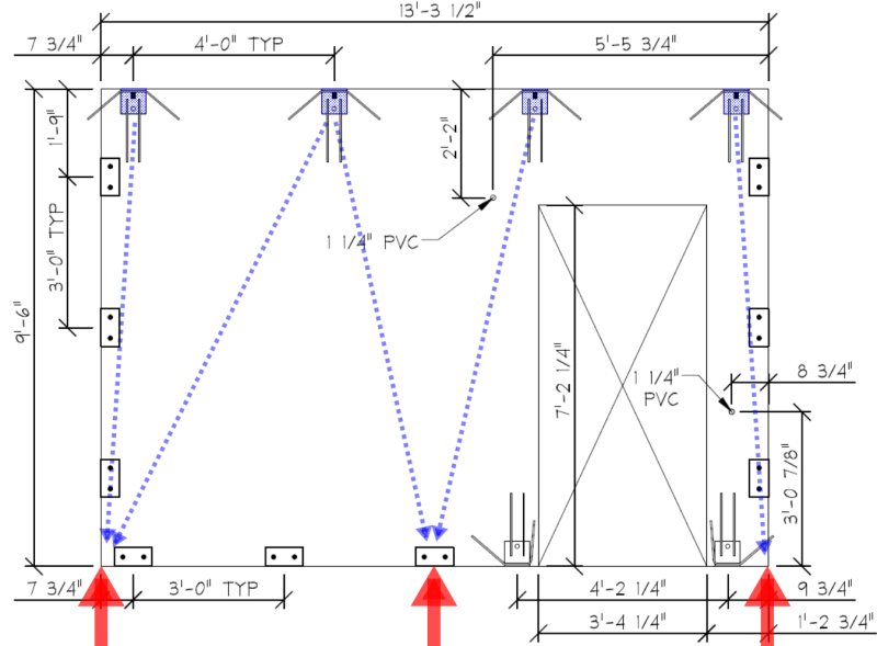
 
 http://files.engineering.com/getfile.aspx?folder=51438201-8c4e-4c5d-9412-a1df411cc236&file=scan_000592.pdf
P1ENG said:
I want to use the sidewalls of the 10'x14' unit to span piers (0', 7', and 14').

Is there a CIP grade beam or slab thickening that 'spans' between the 7' pier spacing, under the wall length/s?
 
Ingenuity, no there is not. This request is client driven. Normally the units sit on a perimeter trench footer with or without slab.

Juston Fluckey, SE, PE, AWS CWI
Engineering Consultant
 
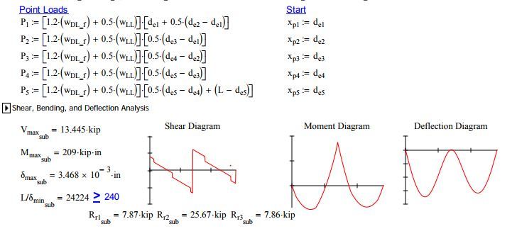
I don't have any software that would do the analysis for me (I don't think RISA-3D will), so I did the analysis in MathCAD with conservative assumptions I believe. Take a look at the attached calculation if anyone would like to review it and give me their thoughts. I also provide a W-beam alternative to the deep beam at the end of the calculation that I wish they would have been good with, but they didn't want the beams. I do pride myself on nice formatting and flow of calculations (maybe not 100% to my standards on this one), but hopefully they are easy to review.

Juston Fluckey, SE, PE, AWS CWI
Engineering Consultant
 
 http://files.engineering.com/getfile.aspx?folder=6e8c648b-e6c4-4638-bf7f-0a3f3d9a5e72&file=Deep_Beam_Calc.pdf
Gee whiz! I won't even try to check that. But just one thing about my comment above. When I referred to "deep beam", I just meant the door head, not the whole wall. So the tie in my analogy would be the bar running across the head of the opening. But again, with this very small structure, the slab above the opening should redistribute the load just fine, as per BA's post.
 
If you have the wall globally supported by 3 piers (RED arrows at 7' c/c) and the floor loads 'dump' their loadings via 4x cast-in 'patch' connections (BLUE color) then these forces are going to 'flow' something like this, which will be in keeping with what BA stated above (I think):

SIDEWALL_vggthq.png
 
Ingenuity,
It seems the 'patch' connections are arbitrary points in that diagram for the load lines. Maybe you will agree if I tell you the roof sits on top of the wall so it is continuously bearing on the wall (i.e. it is not hung on the inside of the wall with a welded connection). Also you say the floor dumps its loads into the wall via the 4x patch connectors, but the floor loads the wall through a tensile force in the 5x patch connectors (I am making them change them all) at the base of the wall. Regardless, I think that diagram would be a fine truss model. You say strut and tie and concrete is the weakest of my materials knowledge, so perhaps "truss" = "strut and tie"?

hokie,
I think I follow you. My analysis turned into a beam with a hole in the web instead of an actual truss design. Ingenuity's drawing would be closer to the truss design you are intending and I might've done, but it seemed the beam analysis was easier for me.

Ultimately I now feel comfortable that the structure will span piers sufficiently. My only concern now is passing the SoCal local reviewer, or if any of you find a flaw in my approach.

Juston Fluckey, SE, PE, AWS CWI
Engineering Consultant
 
P1ENG said:
Maybe you will agree if I tell you the roof sits on top of the wall so it is continuously bearing on the wall (i.e. it is not hung on the inside of the wall with a welded connection).

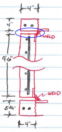
Oh, ok, a better detail, but a previous wall section by you had this:

Capture_wfw6ep.png


So is the top of wall/underside of slab gets grouted to provide 'continuous bearing'?

I would use strut-tie method to design the wall.

Keep in mind that your wall panel is pretty slender [l[sub]c[/sub]/h = 28.5] so since it is > 25 you cannot use ACI 318 § 14.5 Empirical Design Method for walls.
 
I agree in essence with the sketch presented by Ingenuity. If the piers are not already in place, it might be a good idea to move the exterior ones a little closer together, say 12'-0" c/c instead of 14'-0", putting less eccentricity on the 4" x 14.75" column beside the door but it is a minor point.

Like hokie66, I have not checked the calculation and in practice, would likely do a quick hand calculation using very conservative assumptions.

I am not current with the latest codes, but the high slenderness ratio of the walls and column would be a concern to me, particularly in an area of high seismic activity. You may wish to give this further consideration or seek additional comments from Eng-Tips.

BA
 
Ingenuity: Sorry, I should have been clear in that detail. I was just showing the separate pieces (top chord, web, bottom chord) and that a connection is used to transfer the longitudinal shear of a composite action beam. In reality, there is no separation between the pieces. Everything is in complete bearing before getting welded up.

BA: The 4" x 14.75" column is welded to the endwall, so it has additional stiffness to resist the small eccentricity. However, I will certainly try to move them inward since the pier diameters are so large (see below) I don't need them sticking out 1.5' past the unit. I'm sure what is driving this all is they want to auger and use sonotubes instead of excavating for a standard footer.

I expect the piers to be plenty large such that point supports are likely conservative. The three piers are likely going to be 3' in diameter, so 6' (1.5'+3'+1.5') of the 14' length will have bearing. I use ACI 318-14 conform to the requirement of section 11.8 for analyzing the slender walls per that section. I go through the iterative process of checking P-Delta. The walls/columns are close to unity on the checks, but it looks like they are good for the ~28 kip reaction I am getting at the center support. I didn't want to bore you all with my entire calculation!

I appreciate everyone's input. You have brought up some good points, and set me on the track to what I have so far. I think I have addressed or considered your recommendations in my own way so far (beam vs strut-tie being the main variance). Please still free to question me though! Another justification I have is that even though this is high seismic, it would never occur with the beam analysis I performed. The design roof and floor loads are 150 psf and 200 psf respectively (which I am designing the beam for since they are the design loads even though it would never see those loads), but there is no chance of either of those loads being present during seismic activity.

Juston Fluckey, SE, PE, AWS CWI
Engineering Consultant
 
P1ENG said:
design roof and floor loads are 150 psf and 200 psf

What is the proposed use/occupancy of the structure - a storage facility of some type - that is a significant floor loading?

P1ENG said:
standard footer

Don't let Ron see you use the term "footer " - he will correct your swiftly - it is 'footing ' :)

For example:
thread507-376022
thread507-400615
thread507-408833​
 
It is a telecommunication building. They put the large roof live load on there in case of ice impacts from the antenna. The floor live load is due to the possibility of battery racks (only a small footprint though). I don't bother to ask where the batteries go, so I just design the entire floor for the large live load.

I can't be changed! I'm too far in. [wink] Just like I will never pronounce RISA as REE ZA, it is RY ZA to me.
Juston Fluckey, SE, PE, AWS CWI
Engineering Consultant
 
P1ENG said:
I don't have any software that would do the analysis for me (I don't think RISA-3D will)

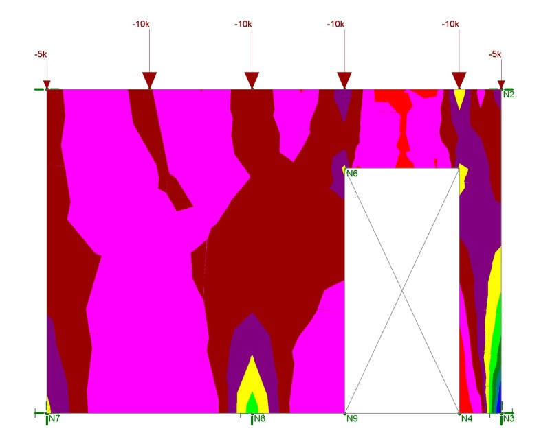
RISA-3D (aka 'RY ZA' for you :)) would make 'light work' out of this panel:

WALL_PANEL_ryljpb.jpg
 
I must know how your doing those MVD diagrams. Any chance you feel share-y? I'm a MathCAD guy and have a version of this but yours is clearly much better.

Capture_04_bozawd.jpg


I like to debate structural engineering theory -- a lot. If I challenge you on something, know that I'm doing so because I respect your opinion enough to either change it or adopt it.
 
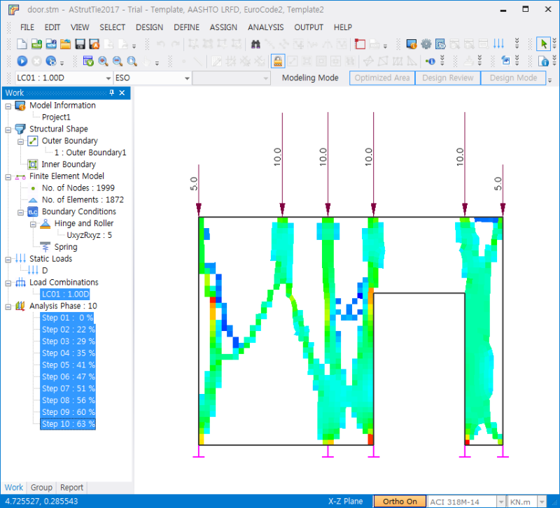
The stress flow is clearly visible. As the stresses flow in the vertical direction, horizontal reinforcement should be placed.
img_181_wuvpqp.png
 
Ingenuity,
Did you do a wall panel or plate elements? I don't know how to take the stresses/forces and correlate that to reinforcement.

Koot,
Thank you. I wrote this one myself and, sorry, I don't want to part with it. I consider it proprietary as I think it gives me an advantage. Also, if you expanded the collapsed area, you might just get confused! I will tell you that it uses singularity functions. I currently have it so I can define (10) support locations, (10) point loads, (10) distributed loads, and (10) ramp loads (drifted snow). I can increase that in the future if there ever is a need. I also have not had the need for applied moments, but I guess I could also include those. Each support location has a boundary condition associated with it so that I can do simple supports, fixed ends, or single supports. To get the graphs, I step along the beam in some interval (usually an inch divided by some tolerance factor [2=1/2", 4=1/4", etc.]) to keep the graphs smooth. The problem is keeping the vectors of the shear, moment, and deflections eats up a lot of size. I dump everything else to keep the size down, but I can easily get to 30 MB file sizes on a full system calculation.

Lim,
Thanks for the effort. Looks similar to Ingenuity's stresses in his last post. With my reinforcement, it looks like I have a capacity of 13.16 kip/ft when I consider the concrete and shear reinforcement.

Juston Fluckey, SE, PE, AWS CWI
Engineering Consultant
 
P1ENG said:
Did you do a wall panel or plate elements? I don't know how to take the stresses/forces and correlate that to reinforcement.

Wall panels. If you assign Wall Design Rules in RISA-3D it can 'design/check' your panel using the Wall Panel Editor. Info here: Link
 
Status
Not open for further replies.

Part and Inventory Search

Sponsor