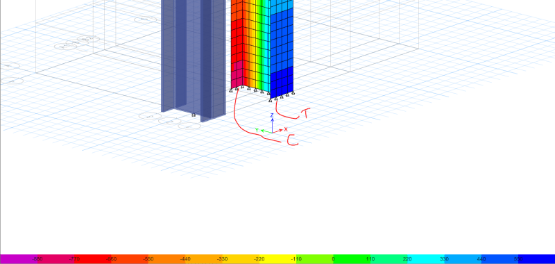
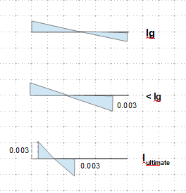
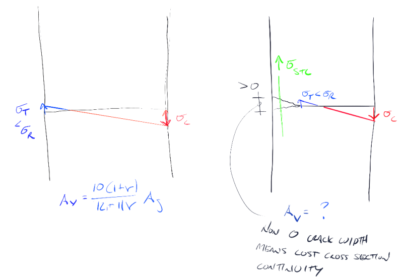
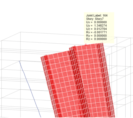
Hi all, I wanted to inquire about how some of you perform your iterative design process for concrete shear wall crack factors and also discuss my current methodology. I am hopeful that I may be able to create a more efficient process and try to hone down on what may be considered more of a standard “industry practice.” Please note that for this discussion I am discussing the stiffness factors for concrete walls used for design under factored load combinations (not serviceability) as per ACI 318-14 sec 6.6.3.1.1a. Also note that seismic does not control therefore this discussion will strictly pertain to wind loading and linear, pre-yield behavior of the structure.
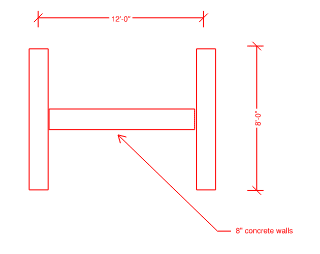
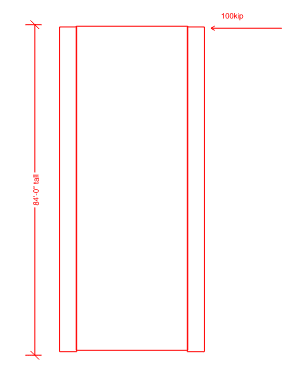
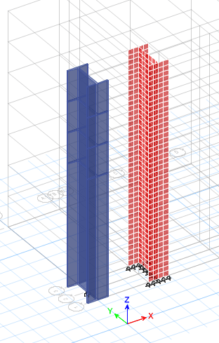
Scenario: 20 story concrete structure with (3) shear wall “groups” that make up a “shear core.” Each shear wall group consist of (4) walls that form a rectangular shape.
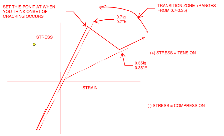
Iteration 1: My first iteration is performed with all walls uncracked using .70Ig -> plot results -> All walls that are ‘cracked’ have their respective cracked factors modified to .35Ig to represent Iteration 1 results (This is done at a per level, per wall basis).
Iteration 2: Using the updated wall crack factors from Iteration 1, I perform a 2nd iteration of the model with crack factors of .35Ig on walls that cracked in Iteration 1, and .70Ig for uncracked walls -> plot results -> Walls whose status match their crack factor remain as is (cracked stays cracked, uncracked stays uncracked, remaining walls have their factors adjusted to match iteration 2 results.
Iteration 3 & beyond: Continue to adjust factors as discussed in iteration 2 until all values converge
At this point I should clarify that the ultimate goal is to have all cracked factors for each individual wall segment at each floor converge with the input factor when checked for all load combinations. This means that if a wall is shown to crack in any of the checked load combinations, then this wall shall have an input of .35Ig and vice versa if the wall is shown to remain uncracked when checking all load combinations, this wall will have a .70Ig.
The issue that I come upon is that I end up chasing my tail when limiting myself to only .35/.70Ig. As you change the stiffness of individual wall groups, you are modifying that load path and subsequently distributing more load to adjacent wall panels. By limiting myself to .35/.70 it seems as if I am trying to say everything is either “white or black” and ultimately consecutive iterations are mere inverses of the previous results. It would appear that in order to accurately reflect conditions, I would need to find “effective” moment of inertia’s for each respective walls segment, but this would be a very time consuming process when one is forced to do this by ‘hand.’ This need for an effective stiffness becomes apparent when one sees the results constantly inversing between 2 sets of walls flashing between “cracked and uncracked” when in reality the wall groups share this load and are somewhere in between.
I have heard from a colleague that "once a wall cracks it is cracked." This is an obvious statement, however it is a more complex issue when we as the engineers are telling the programs which walls are cracked/uncracked and subsequently manipulating where the load is to go. I am under the belief that in a perfect world I would create effective moments of inertia for each individual wall segment (per floor), however I am curious to see how far other engineers/companies take this design approach to get a stiffness model that accurately represents the intent.
I am also curious to find if I am overthinking this and if the general engineering community uses a cracked factor of 0.5Ig for all entities as allowed in ACI 318-14 Section 6.6.3.1.2

