Continue to Site

Eng-Tips is the largest engineering community on the Internet

Intelligent Work Forums for Engineering Professionals

  • Congratulations waross on being selected by the Eng-Tips community for having the most helpful posts in the forums last week. Way to Go!

Concrete Shear Wall Stiffness Adjustment Factor – Iteration Process Discussion 11

Status
Not open for further replies.

polskadan

Structural
Nov 8, 2011
21
US

Hi all, I wanted to inquire about how some of you perform your iterative design process for concrete shear wall crack factors and also discuss my current methodology. I am hopeful that I may be able to create a more efficient process and try to hone down on what may be considered more of a standard “industry practice.” Please note that for this discussion I am discussing the stiffness factors for concrete walls used for design under factored load combinations (not serviceability) as per ACI 318-14 sec 6.6.3.1.1a. Also note that seismic does not control therefore this discussion will strictly pertain to wind loading and linear, pre-yield behavior of the structure.

Scenario: 20 story concrete structure with (3) shear wall “groups” that make up a “shear core.” Each shear wall group consist of (4) walls that form a rectangular shape.

Iteration 1: My first iteration is performed with all walls uncracked using .70Ig -> plot results -> All walls that are ‘cracked’ have their respective cracked factors modified to .35Ig to represent Iteration 1 results (This is done at a per level, per wall basis).
Iteration 2: Using the updated wall crack factors from Iteration 1, I perform a 2nd iteration of the model with crack factors of .35Ig on walls that cracked in Iteration 1, and .70Ig for uncracked walls -> plot results -> Walls whose status match their crack factor remain as is (cracked stays cracked, uncracked stays uncracked, remaining walls have their factors adjusted to match iteration 2 results.
Iteration 3 & beyond: Continue to adjust factors as discussed in iteration 2 until all values converge
At this point I should clarify that the ultimate goal is to have all cracked factors for each individual wall segment at each floor converge with the input factor when checked for all load combinations. This means that if a wall is shown to crack in any of the checked load combinations, then this wall shall have an input of .35Ig and vice versa if the wall is shown to remain uncracked when checking all load combinations, this wall will have a .70Ig.

The issue that I come upon is that I end up chasing my tail when limiting myself to only .35/.70Ig. As you change the stiffness of individual wall groups, you are modifying that load path and subsequently distributing more load to adjacent wall panels. By limiting myself to .35/.70 it seems as if I am trying to say everything is either “white or black” and ultimately consecutive iterations are mere inverses of the previous results. It would appear that in order to accurately reflect conditions, I would need to find “effective” moment of inertia’s for each respective walls segment, but this would be a very time consuming process when one is forced to do this by ‘hand.’ This need for an effective stiffness becomes apparent when one sees the results constantly inversing between 2 sets of walls flashing between “cracked and uncracked” when in reality the wall groups share this load and are somewhere in between.

I have heard from a colleague that "once a wall cracks it is cracked." This is an obvious statement, however it is a more complex issue when we as the engineers are telling the programs which walls are cracked/uncracked and subsequently manipulating where the load is to go. I am under the belief that in a perfect world I would create effective moments of inertia for each individual wall segment (per floor), however I am curious to see how far other engineers/companies take this design approach to get a stiffness model that accurately represents the intent.

I am also curious to find if I am overthinking this and if the general engineering community uses a cracked factor of 0.5Ig for all entities as allowed in ACI 318-14 Section 6.6.3.1.2 😊.


Replies continue below

Recommended for you

EZbuilding said:
Correct me if I am wrong KootK, but I believe in this process the analysis considers the core's total stiffness, but design each face of the core for the load it experiences.

Unless I'm mistaken, I believe that you've described what I feel is one of the bizarre idiosyncrasies of the ETABS design process. Flexural capacity will be allocated as you've described above which:

1) Does provide enough aggregate flexural capacity.

2) Is not really how anybody would reinforce a compound shape, flexural member by hand and;

3) Results in more reinforcement further from the extreme tension face which would compromise stiffness to a degree.

As somebody said previously, this is just the best that we can do for now so we roll with it.

KootK said:
3) Stuffing #2 into ETABS, PERFORM 3D, or whatever the latest fad is and aggressively marketing the results as boundary pushing innovation that only the insiders are capable of.

I realize now that it's been sounding like I have some kind of beef with the CSI products. I don't, at all. My comments would apply equally to any FEM package and are more about the particular users of the software rather than the particular software package. This is almost a disadvantage of CSI's incredible success. In my brain, ETABS = BIM Structural like KLEENEX = the stuff I wipe my nose with.


EZbuilding said:
I have once considered the longitudinal shear between cores of a shear wall before in a more complex core configuration. We were able to justify it as acting as a composite group at the time.

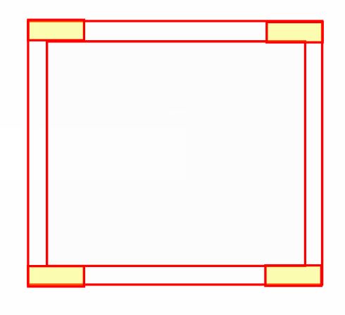
1) My experience has been the same. Usually the column-ish ties that you'll provide to the zones will be more than enough to get this job done and, if anything, I suspect that this is one of the better legitimate reasons to divide zones up into overlapping sections. Otherwise, the layout shown below would be just fine and, perhaps, more constructible.

2) One thing that makes things worse for this is that, unlike with composite steel design, a concrete design has to consider the peak longitudinal shear stresses at any point rather than laying claim to an averaging of the demand over the interface. This comes up often when somebody wants to put a vertical construction joint into a shear wall.

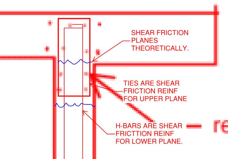
3) For small zones, I sometimes worry about shear friction on a plane take just outside of the zones. You always have enough horizontal bar to handle shear friction there but you don't always have full development on those bars within the zones. I don't sweat this too much though since I'm not all that sold on the whole [shear fricition = fy development] thing anyhow. You know, that and the fact that nobody in the history of mankind has every heard of such a failure taking place.

C01_dhi48i.jpg
 
JP said:
What good is a 5% reduction in force from your analysis if you screw up the construction documents with bad detailing?!

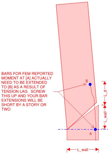
The most egreggious detailing fail that I see routinely in FEM shear wall design is shown below. It's like our brains turn off shortly after our computers are turned on. This one's super easy to spot too. If I see that that somebody has terminated shear wall zone bar within the first couple of stories, I know that I'm dealing with the uninitiated.

C01_lklqxq.jpg
 
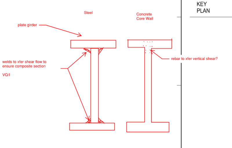
Just so I am clear on this longitudinal shear concept here... A few clarify images/comments:

For steel to make a composite section you need to ensure shear flow between the connected flanges and webs... is this the same for concrete core walls?

image_ocvvpp.png


S&T
 
Almost. As I see it, it's your horizontal bars and zone ties acting as your SF reinforcing.

C01_n48crb.jpg
 
KootK, that makes senses on a shear friction check... my mind went to the vertical rebar type check similar to our longitudinal welds in plate girder.

The method I had in my mind would be difficult to figure out how many pieces of rebar are effective in resisting shear flow across a theoretical plane.

S&T
 
KootK said:
As I see it, it's your horizontal bars and zone ties acting as your SF reinforcing.

Thank you! I was about to write something similar. Then, I started 2nd guessing myself. In the low rise buildings that I've worked on, we usually designed the walls as if they were separate. Added in some end zones ties maybe. But, pretended the walls didn't connect with each other except at floor levels. Therefore, I figured it best to let someone else with more experience reply.... So, thank you for clearing that up!
 
You're most welcome Josh. Until EZbuilding building mentioned his longitudinal shear check, I'd been operating under the assumption that I might be the only engineer on the planet to have thunk this particular thought. And I'd encourage everybody to table this issue gently with their superiors and colleagues lest they be tagged with the career killing "over thinker / analysis paralysis" tag. I should probably get a T-shirt to that effect.

Actually, somewhere in Paulay and Preiestly's tome, I'm pretty sure that they look at a similar issue for the corners of basement walls when the basement is used as a monstrous, stabilizing box for overturning purposes. There, they conclude that vertical bar is required in the joint because the joint may not be long enough for an "around the corner" transfer of strut compression as is the case with taller walls. This is sort of heading in the direction that sticksandtriangles was heading I suspect.
 
From the IStructE Manual for the design of concrete building structures to Eurocode 2:

5.6.4.2 Intersecting walls
Where the composite action of intersecting walls to form a core is assumed the interface shear should be checked in accordance with EC2, Clause 6.2.4 Shear between web and flanges.

Found on Page 91


Nice... thanks for reporting back on that Trenno. I feel like less of a load path weenie now.
 
So what's the consensus here?

Should we pursue an automated linear elastic approach that iterates the stiffness of walls based on codified equations for Ieff?
OR
Should we pursue a non-linear approach with layered shells?

Would like to hear Agent666's opinion.

 
What a thread, what a read! The amount of salt being poured out is quite incredible. I salute and thank you all for your opinions, mostly because they to large extent validate my own. Let me join in as I have watched designers average longitudinal stress across the entire height of a building core and I can no longer stay silent. My personal nemesis are stress concentrations around core openings. When modelled properly the fully-fixed coupling beams distribute flexural stresses very unevenly to the inevitably short wall sections around lift openings. This results in very high design loads at such locations and I am tired of being yada-yada'd away and watching some of my more agreeable colleagues take over.

Regarding "to iterate or not to iterate" dilemma - I think that no amount of fudging of an inherently linear FEM model can yield a physically accurate result for a concrete structure. Representative? Yes. Accurate? No. Besides when approaching an iterative problem it is important to first establish that the iterative approach converges; then it is important to establish that the iterative approach converges to a correct solution. I think that the following two things are major hurdles:

1. Design loads that typically get applied to a structural model are somewhat arbitrary approximations at best; they are backed by good research and decades of experience, however they are not perfect. I think that starting with arbitrary loads, then iterating Ig values and expecting accurate results is just not a sound line of design reasoning.​

2. Once/if one does begin iterating Ig values across an entire structure I am just not convinced that one will not end up in an endless loop chasing their tail. The OP has already stumbled onto this fact and I think that no matter how refined the adopted Ig scale is one will likely end up in a maze with no end.​

I think that a more viable solution is the one suggested by @Kootk - a set of building-wide Ig values for walls/columns/beams. Is such approach accurate? Hell no, such approach is doomed from the onset (see point above regarding nature of design loading). Is such approach representative? I hope that it is because in the essence it is the state of current code guidance and it is what I use in my FEM models.

Lower Ig values are certainly more conservative for SLS states and thus safer to adopt. They assume concrete cracking and it is important to bear in mind that concrete cracking is a cornerstone of concrete design. The only issue I have with lower Ig values is that they yield lower seismic loads...which is a broader debate but then again if we assume in ULS design that concrete is generally allowed to crack then we have to carry this assumption through into analysis.

Physically accurate modelling begins with design loads and lies in the land of performance based analysis and true non-linear FEA modelling. This land is a dark place and my opinion is that we are only just starting to chip away at it. My only worry is that the incentives may not be there as the focus is being shifted away from material savings and towards building program savings (once again, this is just my perspective).
 
Great post, Captain Slow.

Your 1) point has always urked me. We can calculate numerous factors with big fancy equations with endless analysis. On the other side of the Demand v Capacity equation, we just say "oh this building is X type, so it takes Y load."

I'm sure there is some sort of quote out there that says something along the lines of: "it's not so much about whether you need that amount of rebar, it's more about whether you need the beam in the first place."

 
Status
Not open for further replies.

Part and Inventory Search

Sponsor

Top