Continue to Site

Eng-Tips is the largest engineering community on the Internet

Intelligent Work Forums for Engineering Professionals

  • Congratulations waross on being selected by the Eng-Tips community for having the most helpful posts in the forums last week. Way to Go!

Concrete Shear Wall Stiffness Adjustment Factor – Iteration Process Discussion 11

Status
Not open for further replies.

polskadan

Structural
Nov 8, 2011
21
US

Hi all, I wanted to inquire about how some of you perform your iterative design process for concrete shear wall crack factors and also discuss my current methodology. I am hopeful that I may be able to create a more efficient process and try to hone down on what may be considered more of a standard “industry practice.” Please note that for this discussion I am discussing the stiffness factors for concrete walls used for design under factored load combinations (not serviceability) as per ACI 318-14 sec 6.6.3.1.1a. Also note that seismic does not control therefore this discussion will strictly pertain to wind loading and linear, pre-yield behavior of the structure.

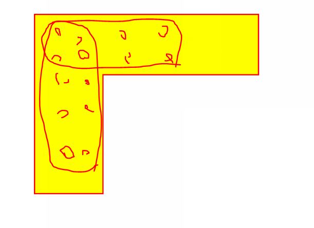
Scenario: 20 story concrete structure with (3) shear wall “groups” that make up a “shear core.” Each shear wall group consist of (4) walls that form a rectangular shape.

Iteration 1: My first iteration is performed with all walls uncracked using .70Ig -> plot results -> All walls that are ‘cracked’ have their respective cracked factors modified to .35Ig to represent Iteration 1 results (This is done at a per level, per wall basis).
Iteration 2: Using the updated wall crack factors from Iteration 1, I perform a 2nd iteration of the model with crack factors of .35Ig on walls that cracked in Iteration 1, and .70Ig for uncracked walls -> plot results -> Walls whose status match their crack factor remain as is (cracked stays cracked, uncracked stays uncracked, remaining walls have their factors adjusted to match iteration 2 results.
Iteration 3 & beyond: Continue to adjust factors as discussed in iteration 2 until all values converge
At this point I should clarify that the ultimate goal is to have all cracked factors for each individual wall segment at each floor converge with the input factor when checked for all load combinations. This means that if a wall is shown to crack in any of the checked load combinations, then this wall shall have an input of .35Ig and vice versa if the wall is shown to remain uncracked when checking all load combinations, this wall will have a .70Ig.

The issue that I come upon is that I end up chasing my tail when limiting myself to only .35/.70Ig. As you change the stiffness of individual wall groups, you are modifying that load path and subsequently distributing more load to adjacent wall panels. By limiting myself to .35/.70 it seems as if I am trying to say everything is either “white or black” and ultimately consecutive iterations are mere inverses of the previous results. It would appear that in order to accurately reflect conditions, I would need to find “effective” moment of inertia’s for each respective walls segment, but this would be a very time consuming process when one is forced to do this by ‘hand.’ This need for an effective stiffness becomes apparent when one sees the results constantly inversing between 2 sets of walls flashing between “cracked and uncracked” when in reality the wall groups share this load and are somewhere in between.

I have heard from a colleague that "once a wall cracks it is cracked." This is an obvious statement, however it is a more complex issue when we as the engineers are telling the programs which walls are cracked/uncracked and subsequently manipulating where the load is to go. I am under the belief that in a perfect world I would create effective moments of inertia for each individual wall segment (per floor), however I am curious to see how far other engineers/companies take this design approach to get a stiffness model that accurately represents the intent.

I am also curious to find if I am overthinking this and if the general engineering community uses a cracked factor of 0.5Ig for all entities as allowed in ACI 318-14 Section 6.6.3.1.2 😊.


Replies continue below

Recommended for you

This would be an interesting video to watch, if you have 7 minutes. Link - "Design Stress -Strain Curve for Concrete"
 
celt,

I'm not sold on it either way as in theory for shear the tension steel should still be holding things together

Wasn't that your position - " If you have a non-zero crack width in my mind you have lost cross section continuity"? Correct, but I wouldn't call it non-zero crack, rather a fine frack. But a crack is a crack, there is no concrete tensile stress can across, nor shear. The steel is design to connect the parts together, but concrete shear resistance is lost, at least theoretically, because how can we measure/assure the interlock exist between the cracked parts?

Note the crack here is flexural crack. For other type of cracks (shrinkage, temperature), the shear is resisted by shear friction through gravity force and interlock mechanism, or by steel.
 
Yeah poor word choice on my part there. Without some more solid research on the topic I'm more not convinced it is a critical item for design right now, but that may change in the future.

I may try and dig up that PCA Design Handbook referenced in Kootk's image and see if they have some cited references to look into more.

My Personal Open Source Structural Applications:

Open Source Structural GitHub Group:
 
KootK, I'm actually not too sure about the layered shells, but after some research it seems to be the way to go about all of this. As I'm sure you know, even within the same office you can get large variance about how engineers go about a problem. That can be both a good and bad thing. I think we're actually on the same team here, just coming at the argument from different angles. There are so many many things there isn't a black & white answer for.

Are you advocating for codes to become more like textbooks? Chapter on core wall design? Transfer slab design? Where does "Engineering Judgement" come into all of this?

Thanks Sticks&Triangles for starting some tests. Once I get some more free time I'll investigate further too. Perhaps we can start an Eng-Tips test building for this thread, with all the bells and whistles - 60st tower, coupled shear walls, perimeter columns, maybe an ourtigger somewhere? Best design gets a purple star.

 
Josh, is there a way to set this up to go back and forth like a hysteresis model in ETABs?

First, I'm want to clearly state that this is beyond my area of expertise. I haven't done this type of non-linear analysis before. So, I have little more insight into how exactly to set up this model than you do. However, I am pro at navigating the CSi documentation, website and wiki / knowledge base. [wink]

Take a look at the ETABS Watch and Learn video below about performance based design. To me, this is the best place to start.
 
Trenno said:
KootK, I'm actually not too sure about the layered shells, but after some research it seems to be the way to go about all of this.

Is the layered shells business what your firm is doing for shear wall analysis? Surely you must know that much about their operations. I think that it would be of great value to finally know of at least one data point out there in the big old world represented by a firm that is actually walking the walk with the "smartest guys in the room" advanced analysis routine. It would be inspiring and I might have to apply for a job there just to get backstage access to the secret sauce.

Trenno said:
Where does "Engineering Judgement" come into all of this?

It doesn't. There's no such thing as engineering judgment in the absence of:

1) Rigorous testing of a sufficient similitude OR;

2) Established design procedures (these usually have to be corroborated via testing as well).

If those things existed, this thread would not.

Trenno said:
As I'm sure you know, even within the same office you can get large variance about how engineers go about a problem.

This is different. One guy arbitrarily using 0.55 Icr where another uses 0.35 Icr is more nefarious than a simple variation in problem solving technique. Rather, it's applying more or less the same technique with more aggressively chosen input parameters.

Trenno said:
Are you advocating for codes to become more like textbooks?

I'm not. I don't see how adding a couple of prescriptive provisions to a code already full of hundreds of prescriptive provisions would somehow turn it into a loathsome textbook. The codes already prescribe how we should calculate wind loads, concrete shear capacity, and gobs of other stuff that could also have been left to engineering judgement. What's the big deal if they also prescribe shear wall stiffness parameters until the state of knowledge advances to the point where we're able to work them out for ourselves using accepted analysis methods?

Trenno said:
Chapter on core wall design? Transfer slab design?o all of this?

Yes, absolutely. Add raft slabs for good measure too. Not necessarily chapters but definitely provisions and, where warranted, sub-sections. ACI already has some provisions particular to core walls.

The root question here really seems to be how we ought to delineate between things that should be codified and things that should not. My opinion is that codes should be kept as as sparse as possible and only include items where the state of the art is such that:

1) There is confusion within the profession about what should be done and;

2) Different, reasonable engineers are routinely coming up with very different answers.

If shear wall stiffness estimation doesn't fit the bill, I don't know what does.

You seem to come from the libertarian school of thought that views our codes as enemies trying to encroach on our freedoms and creativity. I don't see things that way at all. When codes are structured properly, as they mostly are, I view them as "friendly" assets allowing me to make good decisions on "grey area" topics without having to worry that my competition is going to undercut me merely by having the balls to do so via aggressive analysis choices.


KootK said:
1) There is confusion within the profession about what should be done and;

Don't you feel code have confused us in many areas/ways :) I prefer to see them make things clearer in the commentaries, and make pointed references for learning and finding solutions. Just my 2 cents.
 
retired13 said:
Don't you feel code have confused us in many areas/ways :)

Not at all. In the overwhelming majority of cases, I feel that the code has been a help to our profession rather than an hindrance. Consider two recent, salient examples:

1) Anchorage of steel components to concrete (Appendix D) and;

2) Full continuity steel moment connections under seismic (Nothridge).

In both cases, we were designing these elements in accordance with first principles and poorly applied "engineering judgement". And in both cases, testing and real world performance showed that to be woefully inadequate. So now we have code provisions for these thing to protect us from ourselves and to ensure a uniform standard of practice across the profession. And, as always, there was initially a cadre of engineers out there that felt that the new provisions were just so much freedom limiting code bloat.

Yeah, codes are sometimes imperfectly written. As in all things, however, it is unwise to allow the perfect to be the enemy of the good. Keep the baby, even if it means keeping the bath water.

retired13 said:
I prefer to see them make things clearer in the commentaries.

I'm a big fan of extensive commentaries as well but it must be recognized that, whenever a definitive recommendation is made in commentary, it eventually becomes defacto prescriptive or for real prescriptive. Appendix D was, after all, non-mandatory commentary for a good long time.
 
Trenno said:
KootK, I'm actually not too sure about the layered shells, but after some research it seems to be the way to go about all of this.

Dang Trenno, I also thought you were going to drop some sweet knowledge on us as to how your firm handled this. I thought when you mentioned horizontal and vertical reinforcing % at the beginning you were doing the layered shell business yourself.

Trenno said:
Perhaps we can start an Eng-Tips test building for this thread, with all the bells and whistles - 60st tower, coupled shear walls, perimeter columns, maybe an ourtigger somewhere? Best design gets a purple star.

I'm down, I think we would want to create a respository on github or something of the like where we could swap models back and forth. I think we could do some great stuff for the engineering community to demystify some of this stuff and bring the big boys down off of their pedestals. I agree with KootK, in that there is very little difference between Beams_R_US and Skyscrappers_R_US... with experience breeds confidence. In the end we all do the best that we can and lean on that fact that over the past 100 years, our designs more than likely won't fall down.

JP said:
3) For a performance based analysis, you'd want to define what type of Hysteresis model you want to use for the shear wall.

I get a little lost here, if we were are using layered shells, doesn't the Hysteresis model of the wall just "inherently" pop out from the stress strain type curves we define for the wall? I have done a little bit performance based analysis at my work, but only with ASCE 41 pre-defined hinges and picking a moment curveature relationship makes a lot of senses for hinges... but not so much for layered shells?

S&T
 
SnT said:
I also thought you were going to drop some sweet knowledge on us as to how your firm handled this.

I can provide a data point of interest although it's not going to be anywhere near as intellectually satisfying as what you/we are hoping for.

In 2015 I was working with a skyscraper legend who cut his teeth doing a bunch of the high-rises at Canary Wharf in London. Same guy went on to do a bunch of tall stuff in Tornonto, NY, Vegas, and Calgary. So, naturally, I asked THE question.

His answer was that he divided up all of the compound shear wall cores into individual straight wall segments and left it at that. After I guffawed pretentiously, I pointed out the myriad of ways in which that practice would be inaccurate, inefficient and, occasionally, unconservative. Skyscraper guru defended his method as follows:

1) to date, concern over overly conservative shear walls does not appear to have cost the firm work.

2) this method is simple and efficient to apply and can easily be taught to junior/intermediate staff with easy quality control.

3) this method will be safe in most instances with respect to ULS concerns.

4) the current state of knowledge with respect to concrete shear wall behavior doesn't justify the use of anything more sophisticated.

His opinions, not mine. As you can imagine, I was simultaneously terribly disappointed and impressed by this guy's very pragmatic thoughts on the matter. Older dude. Who knows, maybe he's been forced into fancier analytics since 2015 in a nod to market pressure. Some ANSYS, Grasshopper, AI hybrid or something.
 
KootK said:
His answer was that he divided up all of the compound shear wall cores into individual straight wall segments and left it at that.

Wow, never would have thought big skyscrapers would calc out without taking into account flanges and crazy amounts of coupling. I would have thought deflection would get out of control quickly...

S&T
 
S&T said:
I would have thought deflection would get out of control quickly...
Agreed, but I bet that's why there was this caveat
KootK's Skyscraper Guru said:
3) this method will be safe in most instances with respect to ULS concerns.
 
KootK said:
Yes, absolutely. Add raft slabs for good measure too. Not necessarily chapters but definitely provisions and, where warranted, sub-sections. ACI already has some provisions particular to core walls.

Would be nice if ACI would produce design guides similar to AISC for these items. I don't think the code is the right place for it, but I agree that there is a substantial amount of unnecessary ambiguity involved in a number of the provisions. The closest thing we have is CRSI and the old PCA notes - but even those seemed to fall short of tackling the nuances you are discussing.
 
sticksandtriangles said:
Wow, never would have thought big skyscrapers would calc out without taking into account flanges and crazy amounts of coupling. I would have thought deflection would get out of control quickly...

Correct me if I am wrong KootK, but I believe in this process the analysis considers the core's total stiffness, but design each face of the core for the load it experiences. I.E. in liue of considering the moment capacity of a full box section, this process would only consider the capacity of the tension flange of the core by itself not taking into account any benefit of the "web" flange reinforcement for resisting moment demands.
 
SnT said:
Wow, never would have thought big skyscrapers would calc out without taking into account flanges and crazy amounts of coupling. I would have thought deflection would get out of control quickly...

Sorta depends where you're at with cracking and neutral axis depth for SLS. If you're cracked with a shallow neutral axis depth, your compression flange adds little to flexural stiffness and your tension flange adds less.

An interesting corollary is whether or not one should consider the SLS event to have occurred fresh or after the occurrence of some version of a ULS event that would exacerbate cracking for the next SLS. As far as I can tell, everybody's going with fresh.

jayrod12 said:
Agreed, but I bet that's why there was this caveat

Yup, good eye. Some liberties taken with SLS.

EZBuilding said:
I don't think the code is the right place for it...

EZBuilding said:
...but even those seemed to fall short of tackling the nuances you are discussing.

I'm not sure that I've accurately conveyed how simple my proposal would be. Something like.

Element; %Ig Seismic ULS; %Ig Wind ULS; %Ig Wind SLS

Wall; 35; 50; 75
Coupling Beam; 15; 35; 50

Do this or provide some damn convincing reasons for why you didn't.
<-- already exists a general statement in ACI/CSA.

That's it. I didn't put much thought into the particular values and, frankly, I don't even care all that much. I just want some guidance and a level playing field.

EZBuilding said:
Would be nice if ACI would produce design guides similar to AISC for these items.

Hell yeah it would be nice. It's actually been a longstanding dream of mine to create such a guide myself. The trick is that I'd get lambasted six ways from Sunday on every aspect from engineers disagreeing with me. I figure it would have to be sort of a "survey of common practice and pertinent issues" rather than "design your walls like this jackasses.". You know, in the interests of diplomacy and book sales. Wouldn't want to screw my publisher in the insanely unlikely event that I actually found one.
 
I used to tear my hair out wondering at the particular form of zones like this. How much bar goes in which wall? How do you design the stirrups for longitudinal shear to be able to properly engage the bars in the other wall? What about bi-axial bending of the core? What about closed shaft torsion? Arghh... the complexity!!

Turns out most of these will just be overlapping linear wall designs and nothing a lick fancier than that. To a degree, I believe that even a compound wall, ETABS design will be handled tin a similar fashion.

C01_fqrcrz.jpg
 
KootK - which one are you referencing the overlapping linear wall designs pre or post analysis?
 
EZbuilding said:
Correct me if I am wrong KootK, but I believe in this process the analysis considers the core's total stiffness, but design each face of the core for the load it experiences.

Nope, modeled with boxes literally broken up into line segments with no vertical shear connection between them. I know... that's what makes it so shocking.
 
I would wager 50% of the companies in my area of practice consider as such. The other 50% lean towards considering entire cores in their design - but often without considerations of the topics you raised.

I have once considered the longitudinal shear between cores of a shear wall before in a more complex core configuration. We were able to justify it as acting as a composite group at the time.
 
Status
Not open for further replies.

Part and Inventory Search

Sponsor

Top