Continue to Site

Eng-Tips is the largest engineering community on the Internet

Intelligent Work Forums for Engineering Professionals

  • Congratulations waross on being selected by the Eng-Tips community for having the most helpful posts in the forums last week. Way to Go!

Concrete Slab Fold Depression 5

Status
Not open for further replies.

sauce_man

Structural
Apr 14, 2020
28
Hello,

I have seen some discussion in the past on this and it is really something I want to settle. In my experience, slab depressions frequently occur anywhere in a slab and cannot often be supported in a beam like fashion. I like to think that as long as the area of the fold concrete is confined and rebars are developed, the slab fold can be ignored, although it may add some flexibility. The fold won't necessarily act as a stiff rib type element Thus when modeling, ignore the fold unless a deep enough fold justifies treating the slabs as simply supported. Trying to model the fold will result in greater complexity that may not be necessary.

Often, I have seen the "length of fold" quite large. Sometimes detailed as a function of slab depth, sometimes depression depth. It seems to be in the order of more than twice slab depth to the nearest foot or 1.5'. Can someone shed light on this? Is it to facilitate strut tie? is it simply to limit slope of effective slab thru the fold?

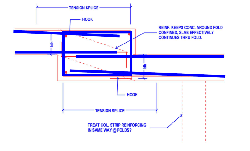
My other concern is that I have a situation where I have a fold very close to a column and slab strip rebar will have to run thru it. As long as bars are developed thru the fold is it enough? in my case the column would be supporting the low portion of slab.

Please see my attached sketch
 
 https://files.engineering.com/getfile.aspx?folder=7b37dcfd-6a35-433e-87a1-8265d3b529a6&file=Fold_Detail.pdf
Replies continue below

Recommended for you

see if you can grab a copy of this document: Reinforced One-Way Slabs with Large Steps

Strut and tie modeling would be the way to go to provide by the numbers back-up for the condition.

A lot of the detailing I see around folds is old rule of thumb type stuff and when less than 2*t ignored in a lot of modeling (unless the slab is PT). You'll run into issues with modeling folds in a lot of the modeling software as the element type used will tend to greatly overestimate the stiffness. I've seen some suggestions to artificially increase the span length to 1-1.5x the fold depth for the spans including folds to give a better deflection approximation and capture some of the additional moment.


My Personal Open Source Structural Applications:

Open Source Structural GitHub Group:
 
I've generally just done the attached...

image_bfz7oy.png


without hooks if bar in compression... but development length with hook for tension if required.

Rather than think climate change and the corona virus as science, think of it as the wrath of God. Feel any better?

-Dik
 
@ Celt thanks for the reference. I have not been able to find anything! I hope it doesn't deviate too much from two slabs. Especially considering slab folds with changes in direction, corners, etc.
 
So that is why I think its reasonable to assume the slab is continuous thru the fold, held together by the detailing. And if the fold is too deep you need an actual beam. you will lose the ability the transfer the moment thru the fold. This is also my concern for high moment regions like at top of column.
 
OP said:
Is it to facilitate strut tie?

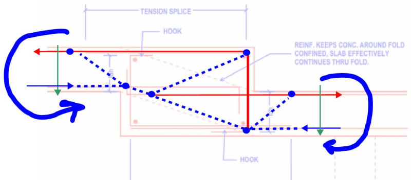
Yes, and I've included such a strut and tie model below. Historically, strut and tie models have not been run explicitly for this kind of situation. Instead, proportions were selected that simply had a high probability of satisfying a strut and tie analysis were such an analysis to be undertaken. But, then, this kind of situation has also historically been limited to regions of low moment demand.

OP said:
So that is why I think its reasonable to assume the slab is continuous thru the fold, held together by the detailing.

To clarify, while the confinement is a benefit in this situation, it is a secondary benefit. The primary goal is to provide a capable moment and shear splice between the upper and lower slabs. In high demand situations, it is certainly not sufficient to simply provide some nominal confinement and call it good. Rather, in high demand situations, I feel that some explicit design should be undertaken.

If you've sketched your proportions accurately, I might actually be inclined to abandon the moment connection and, instead, call this joint a slab pin with the low slap cantilevering from the column to pick up the upper slab. If you follow the strut and tie model through, you may well find that it is an arrangement that works with smaller bars (#4/#5) but is quite untenable when you're dealing with the dense, larger bars typical of slab top mats in the middle strip.

C01_fhyhww.jpg
 
You can model the stepped slab use rigid link connecting the slabs, the result could be unlike a continuous slab, since the fold is much rigid than the slab. Inclined bars follow the dashed lines are often provided by many designers. Watch out for unbalanced live load pattern that leads to higher local stress.
 
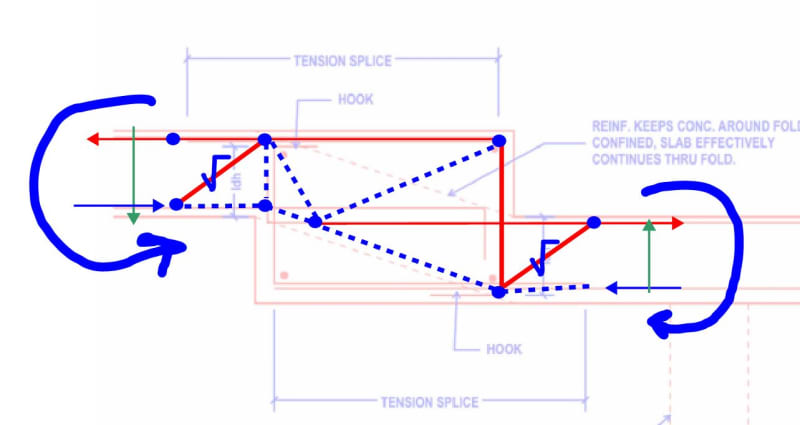
Perhaps it is better to model it like this with the incoming shear struts modelled as ties to reflect diagonal tension and punching shear in the concrete.

C01_jurkuo.jpg
 
Should also note I have a line load from wood bearing walls above at the fold edge. In such a model I would apply T/C point loads = Mu/d, but how would I account for the shear? apply at the bottom of tension ties as you have shown with the blue "check mark"
 
sauce_man said:
In such a model I would apply T/C point loads = Mu/d, but how would I account for the shear?

All of the fancy detailing is really about the moment connection. You're still fundamentally dealing with a slab without shear reinforcement. If anything, you're slab step improves your shear situation by spreading your shear wall chord reactions over a wider width of slab. [3.0 x overall step height] would seem to me a defensible minimum on the distribution width.
 
Thanks Joel

Rather than think climate change and the corona virus as science, think of it as the wrath of God. Feel any better?

-Dik
 
Hi All,

Great thread. In the middle of designing a slab w/fold and am glad I came across this.

Question: In modeling the slab fold using shell elements and a rigid link for the offset between centerline offsets, I end up with a net tension in my slab at the boundaries. Has anyone else experienced this?

Seems as though folks might be focused on detailing the fold to transfer moment but not accounting for the additional tension in the slab on either side of the fold.
 
Status
Not open for further replies.

Part and Inventory Search

Sponsor