Continue to Site

Eng-Tips is the largest engineering community on the Internet

Intelligent Work Forums for Engineering Professionals

  • Congratulations KootK on being selected by the Eng-Tips community for having the most helpful posts in the forums last week. Way to Go!

Concrete strength for a lifting point 2

Status
Not open for further replies.

toothless48

Mechanical
Oct 27, 2014
29
Hello, I work in a small R&D lab. Our CTO had our technician set up a lifting point using a concrete beam in the ceiling of our lab (a week when I was out). I would like to validate the strength of this setup to make sure it is safe, since it was done very ad-hoc.

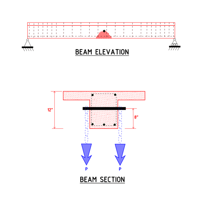
The setup is a 3/4"-10 double threaded stud through an existing ~3/4" conduit sleeve in a concrete beam. The beam's dimensions are 12" in height and 12" in width. The sleeve is 8" from the bottom of the beam. The two ends of the stud are nutted + pinned, and are used to hang chain for a chainfall.

I have done a hand calculation for the stud (125 ksi min tensile strength) assuming two-point beam bending. Using a factor of safety of 5, I found it to have a 700 lb capacity (350 lb vertical load per side).

My question is: how can I validate the strength of the concrete / what should I consider for that analysis? I do not have a lot of experience with concrete analysis, so I would appreciate any insight or references. I do not have access to any of the building plans or technical information. I would also appreciate feedback if it is a bad idea to even try to do a validation for this - I am just trying to do due diligence one way or the other.

Some folks in the office already lifted 600 lb with the setup (again, I was not involved when they did). If we do decide on an actual load capacity, we will test it at 125%.

Thank you
Mike
 
Replies continue below

Recommended for you

So the setup looks something like the following?

beam_ewklzu.png


If so, and assuming the span is not excessive, applied load is relatively small in magnitude and short-term only, then you probably do not need to consider span-type 'global' effects.

You need to check the 'local' concrete failure modes like direct-tension pullout of the existing conduit (possibly a form tie hole?) with through-bolt/stud. Without knowing the existing rebar within the beam, you will either 1] have to assume an unreinforced section or 2} GPR span the beam and determine shear stirrup spacing and longitudinal rebar, and possibly probe the beam to check for rebar diameter.

For direct-tension, if you assumed a 45[sup]o[/sup] failure-plane (actual will be be more like 35[sup]o[/sup] to horizontal) that would give you a failure area of 1.414 *8" * 12" beam width x 2 sides = 271 in[sup]2[/sup]. Assuming a concrete tensile strength of 200 psi (this would need to be verified and also check beam condition for existing concrete cracking in proximity to the connection) and that would give you a pullout strength of 54,000 lb.f

With a through-bolt at failure you will have curvature of the bolt/stud and local high-contact bearing stresses under the invert of the conduit/concrete way before 54 kips.

Seems you will be limited by bolt/stud capacity, or maybe chain capacity depending on the chain size/grade.
 
I agree with Ingenuity regarding checking a simply wedge type failure. Seems you have lots of concrete capacity regarding pull out.

As far as global failure, you are adding to the live load of the floor over. I wouldn't really want someone hanging ~1000 lbs beneath my floor without assessing it.
 
I would not want to put a 54K load on that beam... the beam will fail.

Rather than think climate change and the corona virus as science, think of it as the wrath of God. Feel any better?

-Dik
 
It’d be some chain block! [sub][bigsmile][/sub]
 
I was thinking that there should be a bit of a disclaimer to the effect that failure of the beam may occur long before the load of that magnitude could be applied...

Rather than think climate change and the corona virus as science, think of it as the wrath of God. Feel any better?

-Dik
 
I would have thought the issue is more that if the bolt bends even a little then you can get some local cracking / crushing of the concrete at the shoulders of the hole?

Remember - More details = better answers
Also: If you get a response it's polite to respond to it.
 
With that load, a few things could go wrong...

Rather than think climate change and the corona virus as science, think of it as the wrath of God. Feel any better?

-Dik
 
Thank you Ingenuity for the helpful post (your diagram does represent our situation), I appreciate your time, and everyone else for your advice. This helps a lot with our assessment.
 
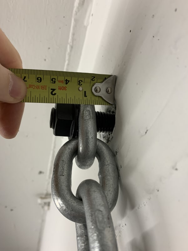
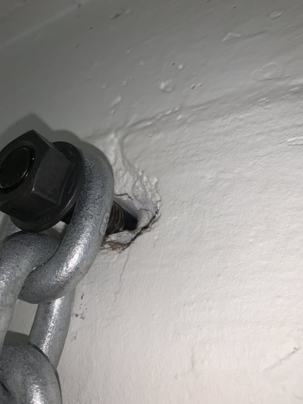
One more question - there are two lifting points that have been set up. The concrete condition in the first is very good, no indications. In the second, near the form ties, there is some missing material (much of which has been painted, so it has been that way for some time). This is more of a basic statics question: for static loads, do irregularities in the surface "de-rate" the static capacity of the member, i.e. act as stress concentrations? As far as I can tell, there is no crack propagation through the bulk material. I know for structural steel, stress concentrations are less relevant, but I am wondering if it is more relevant for concrete as a brittle material.

IMG_1527_p8mngq.jpg

IMG_1541_rfq2b6.jpg
 
Usually the hanger is a stirrup, this will fit close to the beam and minimize the bending of the bolt.
The bolts should be close fitting in the holes also. We used double ended studs so that the center portion was smooth, no bending of threads.
Then make sure that the hoist is small enough. Stencil the max lift on concrete and make it clear that they cannot use a larger hoist.

= = = = = = = = = = = = = = = = = = = =
P.E. Metallurgy, consulting work welcomed
 
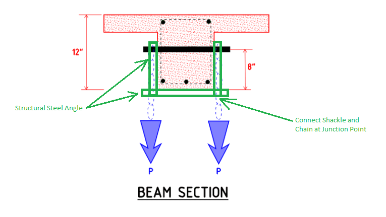
I'd probably use a BAR 1/4x3 and bend it so it slips over the beam just to minimise bending in the pin. Your advice to paint the capacity on the beam is excellent.

Rather than think climate change and the corona virus as science, think of it as the wrath of God. Feel any better?

-Dik
 
I agree that bending of the bolt is your main concern after seeing the photo. The localized spalling of the concrete around the exposed portion of the through-bolt is not so much an issue for the concrete beam as it effectively increases the "cantilever" length of the bolt as the point of fixity or fulcrum gets shifted back further into the web of the concrete beam thus increasing the stress on the bolt. You can eliminate or lessen the bending of the bolt and just rely on direct shear of the bolt by placing your bearing point as close to the face of the concrete beam web as possible. As dik mentioned, perhaps with some bar or angle iron.

Untitled3_o3ett9.png
 
Thank you STrctPono for the input. I agree with your concern. When I did my nominal stress analysis on the bolt, I assumed a cantilever length of 2" to be conservative, which I think is about 0.75" longer than the apparent length.

The steel strap is definitely an interesting idea.
 
I did a global analysis on the overall concrete beam for simple bending. I got a tensile bending stress value of 117 psi. I have to admit my own ignorance (my career so far has mostly involved metal...), I am not sure what to do with that. Based on Ingenuity's post, a conservative assumption for the tensile stress of un-reinforced concrete is 200 psi. I guess that only gives me a safety factor of ~1.7? Ignoring, of course, all the other loads on the beam. I am honestly surprised, I did not expect a 700lb load to be that significant.
 
That’s not how you assess concrete bending strength. Concrete is assumed to have zero tensile strength for bending purposes, and is indeed generally cracked at services loads (Eg cracked at midspan), which is where tensile reinforcement comes in.

For anchorage pullout you do rely on the tensile forces in the concrete, to resist a chunk of concrete tearing out.
 
toothless48,

We don't run stress checks like you would for an isotopic metal in conventionally reinforced concrete... at least not to verify Limit State Design. Any chance you can get your hands on the as-built drawings for your building? There really will be no other way to verify the existing reinforcing steel in the member. You would also need span length, weight of concrete beam and any tributary elements framing into it.
 
Tomfh/STrctPono, thank you, I appreciate the advice. I seem to have found myself slightly out of my depth with this one. I will try to see if the building plans are available, although the building is quite old - at least part of the building was built in 1903.
 
toothless48 said:
I am honestly surprised, I did not expect a 700lb load to be that significant.

I very much doubt that a single 700 lb applied (temporary?) load will be problem - it is basically equivalent to two or three large people in very close proximity, or a steel filing cabinet full of paper files (if such things exist in today's all-digital world).

You stated that you don't have the existing drawings, so I see two immediate options:

OPTION 1:

Visually check the existing beams for any pre-existing distress: excessive cracking, deflection etc. IF all checks out continue as follows:

Measure the existing span/s;
Measure the distance to any parallel/adjacent beams (so as to determine the tributary area as STrctPono stated);
Measure slab thickness;
Measure beam width and overall beam depth.

With above data, calculate the existing dead loads. For example: 20' span beam, 18" o/a depth x 12" wide beams @ 10' centers, with 6" thick slab will yield an existing DL (self weight) of 18,000 lb.f

If the proposed added NEW load is less than 5% of applied DL (900 lb.f in this example compared to new applied load of 700 lb.f) then you are ok.


OPTION 2:

If OPTION 1 does not check out, OR, if this is a 'mission-critical application' then probe and GPR scan the beam and determine existing rebar diameter and spacing, then calculate the flexural and shear capacities and compare to applied actions.

 
toothless48 said:
...although the building is quite old - at least part of the building was built in 1903.

Well then, 'step' carefully.

Under OPTION 2 you may need to consider materials sampling to check rebar grades, concrete properties.

What is the occupancy of the overhead beam/slab to which you have the hanging load attached? A roof, or an occupied floor?
 
Status
Not open for further replies.

Part and Inventory Search

Sponsor