Continue to Site

Eng-Tips is the largest engineering community on the Internet

Intelligent Work Forums for Engineering Professionals

  • Congratulations KootK on being selected by the Eng-Tips community for having the most helpful posts in the forums last week. Way to Go!

Confused how this axis datum B and centerplane datum C constrain any deg of freedom

Status
Not open for further replies.

sendithard

Industrial
Aug 26, 2021
166
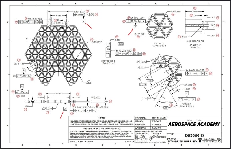
Below is a drawing from titans of cnc educational manufacturing series.

I understand how datum A restricts 3 degrees. If this drawing had datum B and C pointing to the outer wall features creating two planes I understand how that part would be fully locked down.

Where I'm getting confused is when Datums are axis and centerplanes. Datum B is an axis and I don't see how without a dimension to another fixed datum that it isn't free to translate around on datum A or for that matter still spin in Z. Then I look at Datum C and see a centerplane, but again what keeps it from spinning around or translating all over datum A.

Thanks for any help. Below is the drawing and I will attach the complete pdf of all the pages.
sheet2_okhhkp.jpg


Replies continue below

Recommended for you

Nothing "prevents" these things. These datum features are used to locate the parts to the DRF no matter where in the inspection area you care to set it up.

You set up a flat surface against which to confine A, put in a pin to confine B, and then use some sort of clamp to define C. If all these are suitable in relevant form and size and location, then the part is placed into alignment.

A, B, and C datum feature simulators/true geometric counterparts can literally be anywhere on the planet, but the part being inspected has to fit them.
 
Specifically, B is confined to being perpendicular to A wherever A is. And C is confined in location to A and B wherever those are, per their relevant feature control frames.
 
3d,

If a hole feature is used to create a datum axis B is it assumed that that hole has been theoretically placed over a fixed pin that cannot be moved in space? I understand the datum creation and that it is perp to A but I don't understand why that axis cannot traverse all over A's surface. I'm guessing it is bc the part hole feature is theoretically place over a pin bolted down to Datum A at a set location perp to Datum A?


Umm - the datum A is an infinite plane. Datum feature A is bounded by a surface that is limited relative to {A|B|C} so the boundary is fixed relative to those features and cannot wander off.
 
3d,

I'm sorry, I don't understand what you are saying. Datum A is an infinite plane, I get that. The part now only has 3 DOF. Then someone calls out a hole feature in the direct center of the part as datum B. I just don't understand how this constrains it at all. Is the datum B axis not allowed to translate in x and y coordinates? Basically, I 'm asking if that axis is set in stone? If so, I understand how it confines some freedoms, but I don't see anywhere in the drawings where datum B's location is dimensioned from a set datum plane to establish let's say an origin location. All the dimensions for datum B seem to be from some other internal features. So in my mind Datum B can be located infinitely all over the place on datum A.
 
3d,

I'm a CAD guy and I don't understand this datum B axis stuff. Here is my issue....I open up a sketch on the top view(staring at datum A's beautiful infinite surface plate)..... this sketch cannot translate towards me and cannot rotate in x or y. I then draw a circle in the positive x an y quadrant in a random place and do not dimension it's location. I close the sketch. This circle I sketched has the freedom to move all over the damn place of datum A or the top sketch plane. It is not constrained by a theoretical pin location b/c there are not dimensions to hold it down.

I don't understand how the datum B in the above drawing isn't the same as the above description. What is keeping Datum B axis from translating all over the map on top of datum A?
 
So I'm staring at this print more and now wondering if Datum B is the origin? I'm only used to simple drawings where the back left so to speak is the origin. Is my lack of understanding of the true origin affecting my understanding here?
 
sendithard said:
I open up a sketch on the top view(staring at datum A's beautiful infinite surface plate)..... this sketch cannot translate towards me and cannot rotate in x or y. I then draw a circle in the positive x an y quadrant in a random place and do not dimension it's location. I close the sketch. This circle I sketched has the freedom to move all over the damn place of datum A or the top sketch plane.

You are correct until the above quote. Datum axis B is wandering on the plane of A because it has only perpendicular constraint to datum plane A.
Now look at datum feature C, whose position is constrained to datum axis B. Look at part note #2. All other feature's are constrained to A in orientation, B in location, and C in another orientation. Hence, datum axis B is the origin of measurement of that general profile (location) tolerance to DRF A|B|C.

sendithard said:
What is keeping Datum B axis from translating all over the map on top of datum A?

Nothing keeps datum axis B from translating. It keeps the other features from translating.
You setup a physical DRF as 3DDave advised in his first reply and put the part on the setup then your part is constrained to DRF.
 
sendithard,

In the same way that the circle (or really more applicable to the example in question - cylinder) itself is able to translate in (x,y) in 3D space so too is the plane able to translate in (z) and rotate and (u,v) itself. Its not that these features are constrained to some arbitrary reference in 3D space, they ARE our reference and the part and its corresponding features are constrained TO THEM, as are any lower precedence datum features ie: Datum Feature C itself* constrains (w) which is constrained in (u,v) wrt Datum Feature A and (x,y) wrt Datum Feature B which itself constrains (x,y) which is in turn constrained in (u,v) wrt Datum Feature A which constrains (u,v,z).

*Actually B and C work together to constrain (w), but I simplified it for the sake of my example.
 
Thanks everyone, I think I got the understanding now. So as you place the part on a surface you define A, then you place B over a pin to define where B is, then am I correct you can spin the part in any angle away from y that you want as long as at some point you clamp it down which then defines the C centerplane orientation in a typical xy grid?
 
In very simple terms, yes - mostly.

you can spin the part in any angle away from y that you want as long as at some point you clamp it down which then defines the C centerplane orientation in a typical xy grid

Not always - its not always necessary or even desirable to constrain all 6 DOF.

They typical example is to imagine a part with two keyways like Y14.5-2009 fig 4-40/4-41. One could set one keyway as a datum feature B, and constrain [w] rotation when specifying the tolerance zone for the second keyway by utilizing DRF A|B. But if we don't care if they are aligned then we can specify only A as our DRF for both tolerance zones (along with SEP REQT) and leave [w] free so that their orientation/clocking wrt each other is not locked.

An even easier example would be to imagine just a round shaft without any keyways or any other features. There is no need to constrain [w] rotation as we have no features that we care about their orientation/clocking in that direction, and indeed we aren't even able to as we don't have any features which are able to constrain this DOF.
 
Status
Not open for further replies.

Part and Inventory Search

Sponsor