Continue to Site

Eng-Tips is the largest engineering community on the Internet

Intelligent Work Forums for Engineering Professionals

  • Congratulations cowski on being selected by the Eng-Tips community for having the most helpful posts in the forums last week. Way to Go!

Confusing software terminology 1

Status
Not open for further replies.

Aleeeex

Civil/Environmental
Aug 14, 2020
42
Hi guys,

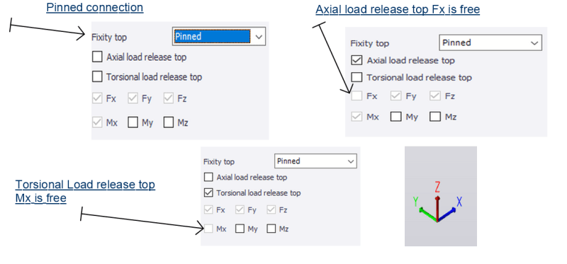
I am just learning a new software and I came across some new terminology I am not sure about like Axial load release top, and torsional load release top and bottom.

I don't understand what axial load release means? the axial force doesn't go through the column like there is compressible material between the column and the bottom flange of the beam so the beam forces don't go to the ground through the column.

Similarly to torsional load release.

image_oahoxm.png


If there is a real connection example with picture with a simple explanation.

Please bare with me!

Thanks
 
Replies continue below

Recommended for you

Hi!
The one with axial load release is when you don't want your column to take axial force as it may be staircase column below your primary beam.So you can provide a clip connection withvertical slots in the clip
 
Software terminology can be confusing. What you can do is try different combinations and check the output.

My guess would be that in the first sketch, the node is fixed against translation in all three axes and is free to rotate about the Y and Z axes but not about the X axis.

In the second sketch, there is a roller in the X direction but the Y and Z direction are fixed against translation. As in the first sketch, there may be moment about the X axis but the node is free to rotate about the other two.

In the third sketch, the node is pinned against movement in all three directions and free to rotate about all three axes.

And it should be "Please bear with me". Your last sentence sounds like an invitation to a nudist colony.

BA
 
Sammy345 said:
I agree with you the axial load release the column would not take any load from the primary beam, however, in my sketch shouldn't the support be free in z direction rather than x dir. what is the maximum deflection the slot can move? how this work?

Thank you


BAretired said:
"And it should be "Please bear with me". Your last sentence sounds like an invitation to a nudist colony."
Why? Are you interested?????? :)
 
I just saw the coordinates. I think there must concept of local and global coordinates .The one you are showing might be global coordinates. It should be similar to Staad
 
I just saw the coordinates. I think there must concept of local and global coordinates .The one you are showing might be global coordinates. It should be similar to Staad said:
Thank you I gathered that however, do you have any example explaining torsional load release?
 
If the column is connected to the primary beam by slotted connection! What forces do you use to design the connection?
 
In general, for pinned connection, you need to restrict the freedom of joint movement/translation in all three directions (Fx, Fy, Fz) to obtain reactions. Then you need to allow the joint to rotate about all axes (Mx, My, Mz - Torsion) to avoid moment and torsional forces.

Your first joint specification tells me that, it is a pinned joint with moment capacity about X-axis (Mx fixed). Your second joint specification is similar to the first, the difference is you will see joint movement in the X direction. You have to read the user's manual for the meaning and application of "Axial/Torsional Load Release Top".

Most programs interpreting direction of forces on global axis system as follows, but you shall double check the user's manual for correctness.
Fx, Fy, Fz - force in the respective axis, positive in positive axis direction.
Mx, My, Mz - moment about the respective axis, counter-clockwise indicate positive rotation (right hand rule).
 
If the column is connected to the primary beam by slotted connection! What forces do you use to design the connection?
 
Natsmith said:
If the column is connected to the primary beam by slotted connection! What forces do you use to design the connection?

Depends on the direction of slots and type of bolts. Slip critical bolts allow for adjustment before tightening but do not allow slip after tightening.

Axial load release in the column means that the beam cannot have a vertical reaction on the column.
Axial release on the beam means the beam cannot receive an axial load from the column.
Torsional release on a member means it cannot receive a torsional moment.

BA
 
very interesting!

Can you please illustrate with practical example of each case, depict them with images so will be more easier to understand.
 
One example is a simple beam parallel to the X axis with hinge at one end and a roller allowing axial translation at the other. The hinge can resist reactions in all three directions (Fx, Fy and Fz). The roller can resist a vertical reaction (Fz), a horizontal reaction (Fy) but not a horizontal reaction (Fx).

A second example is a member where both ends are rigidly connected to other frame members having variable stiffness and variable 3D orientation. End reactions Fx, Fy, Fz, Mx, My and Mz are each possible unless released.

If a vertical reaction (Fz) is to be avoided in a column, but the top needs to be laterally braced, a vertical roller may be used, thus avoiding axial load in the column.

BA
 
Instead of asking someone to draw, why not to take a small quiz, to demonstrate how much you have gained from here. Assume you are going to design the framing shown below, please provide spec for support restraint for analysis purpose, and reasons.

image_dt8zdj.png
 
The column base plate can be either fixed or pinned but I prefer pinned to be honest!
 
When dealing with releases it is important to know if you are dealing with local or global axes, and what the axis convention is.

In a 3D analysis the global vertical direction may be Y or Z, and the other two axes define the horizontal plane. The axis diagram in the bottom right shows that the vertical axis is Z, but the check boxes indicate that the axial direction is x, and the wording suggests that it is talking about vertical columns, so the check boxes seem to be indicating local axes where:

- x is along the length of the member, so vertical
- z (or possibly y) is perpendicular to x in the global XZ plane
- y (or possibly z) is perpendicular to the xz (or xy) plane.

It is also possible that the axes may indicate the local axes of the member connecting to the top of the column, in which case the x axis would be horizontal, which would be consistent with the axis diagram.

If this isn't clearly specified elsewhere in the documentation the easiest way to check would be to run and analysis and see what results had deflections or rotations without an associated force or moment.

Or contact the program support.

Doug Jenkins
Interactive Design Services
 
Yes, you see there is more than one way to specify joint rigidity. You can even specify Mx fixed, yet My stays free. It all depends the situation. Someone might not like the orientation of the column....:) Glad to see that you handled well.
 
Like everyone keeps saying. Local co-ordinates. In this case its seems X is along the beam/column.

Having a local coordinate system for beam fixities makes much more sense, in fact it is kinda unworkable if you don't. Otherwise beam any that is not perpendicular to the global coordinate system is going to give you a big headache.

EDIT:
Oh and axial load and torsional load mean exactly that with respect to the member. That the connection doesn't resist axial load and the connection doesn't resist torsional load. Axial load release would be your typical beam roller support. Torsional load release is a bit more uncommon.
 
It is a pointed advice - try the best to orientate the local coordinates with the global ordinates, otherwise a lot of time will be wasted to figure out the reactions/internal forces, and still making mistakes.
 
Status
Not open for further replies.

Part and Inventory Search

Sponsor