Hi all,
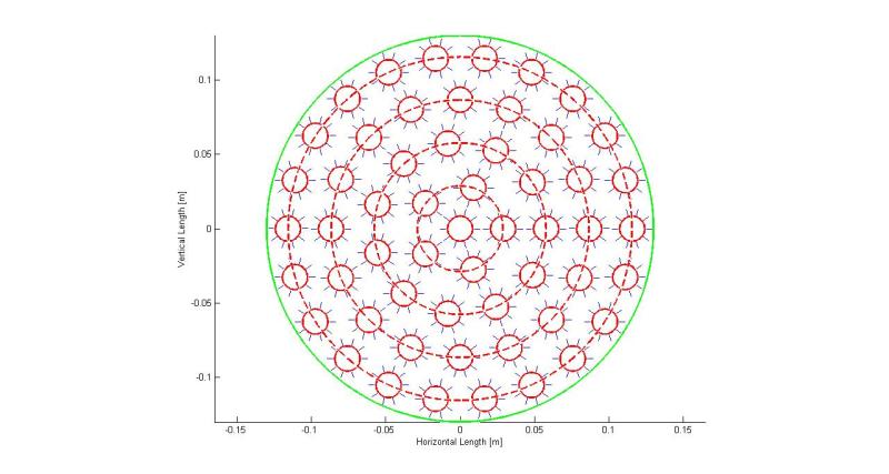
I currently design a multitube heat exchanger. In this heat exchanger multiple tubes are put in parallel, while the flow goes in parallel, so not with baffels for cross flow (due to very stringent pressure drop reqs). The tubes will be longitudinally finned.
I currently struggle a bit with the calculation of the heat transfer coefficient. I model the heat exchanger as a double pipe exchanger with the equivalent heat transfer surface area of the entire device.
The question I do have now is the following:
I do calculate the Reynoldsnumber with the hydraulic diameter of the entire tube bank within the shell to obtain the heat transfer coefficient of the plain tubes. For calculation of the heat transfer coefficient I now am in doubt which hydraulic diamter to use. Shall I use the same as for the calculation of the heat trasnfer coefficient of the plain tubes? Or shall I calculate it based on the area between the ribs? The flow speed is kept the same, such that also the reynoldsnumber is only dependent on the hydraulic diamter.
I am really confused about the hydraulic diameter and its use in the Nusselt number and Reynoldsnumber definition.
thank you for your hints!