Continue to Site

Eng-Tips is the largest engineering community on the Internet

Intelligent Work Forums for Engineering Professionals

  • Congratulations IDS on being selected by the Eng-Tips community for having the most helpful posts in the forums last week. Way to Go!

Confusion over Datum choice on Positional Tol. 2

Status
Not open for further replies.

R1chJC

Marine/Ocean
Apr 15, 2015
51
Hi All,

Perhaps people can help me with a debate we are having at work.

See picture.

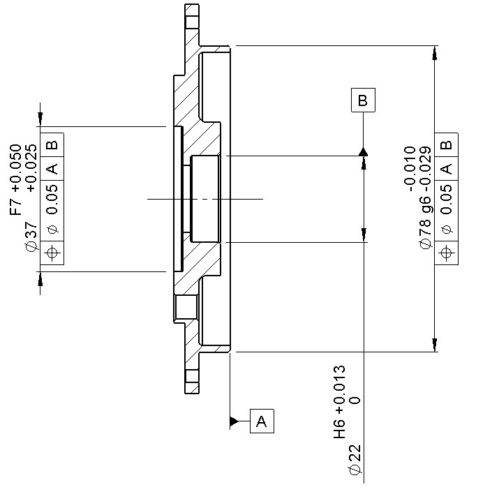
My colleagues are questioning what Datum A brings to the table for the positional call-out on the ∅37. They argue that referencing Datum B should suffice for controlling the concentric relationship between the two bores.
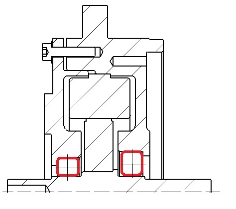
From a functional perspective, the Datum B bore houses one end of a shaft bearing. The datum A face is a spigot/location diameter that abuts to a mating part in the main housing. I want to ensure all bores are concentric. I'm also trying to convince them that using an actual concentric tolerance is not necessary and inspecting it is pure evil..

I thought that having datum A introduces a perpendicularity control. A separate thread here: Link describes something similar and I can follow the train of thought in that post, but i'm having a hard time applying that logic to my example.

I've seen it many times where a positional tolerance for a bore references a perpendicular mating flange face.

We work to ASME.

Thanks all.

Tol_Example_ba03sv.jpg
 
Replies continue below

Recommended for you

Datum B would suffice if the only concern were centering the diameters. But ask yourself (and your colleagues): How does the part function? Does it only touch datum feature B? No -- I suspect the part flattens out on datum feature A. So while perpendicularity does indeed factor into it, I would create my defense based mostly on how the part assembles and how it should be fixtured when measuring the position.

John-Paul Belanger
Certified Sr. GD&T Professional
Geometric Learning Systems
 
There is little use analyzing a single part.

Here's one alternative - this part is mounted onto a shaft using an interference fit on the 22mm diameter identified with B and the 37mm diameter is the sole interference fit guide for another part. The goal is to limit the location and orientation variation between the shaft and the other part. This alternative is one where only B would be of importance to the position tolerance for the 37mm diameter.

Any other surfaces that orient the part or any loop of mechanical connections should be included as datum references.
 
Hi Belanger,

Thanks for the response.

From a functional point of view the part locates into a housing bore on the ∅78 until it abuts onto an internal shoulder on Datum A face. A shaft runs through the housing on a bearing located Datum B.

I'm still struggling to see what Datum A brings to the party.
 
From a functional point of view the part locates into a housing bore on the ∅78 until it abuts onto an internal shoulder on Datum A face. A shaft runs through the housing on a bearing located Datum B.
A follow-up question then... When it abuts onto the internal shoulder, does that shoulder merely stop the motion (i.e., contacts one point)? Or do you have to wiggle the shaft so that it flattens out completely on the shoulder (i.e., contacts three points)?

I'm merely restating Dave's point: If it's an interference fit with one stop point and no flattening onto the shoulder, then your colleagues are correct that datum A is not to be referenced.

John-Paul Belanger
Certified Sr. GD&T Professional
Geometric Learning Systems
 
If the 78mm diameter is the guide, it should probably be a datum.
 
R1chJC,
Are you able to post a sketch showing interfaces for the part in question? The best would be if the sketch not only showed the assembly, but also a bit of information on interface tolerances.
 
Hi All

Belanger, 3D Dave,

The ∅78 is a sliding fit into the mating housing. So yes it is contacting on the single highest point. Therefore any out-of-perpendicularity of that Datum face A has minimal impact on the orientation. However, Datum Face A does perform an important functional purpose of clamping onto the shoulder of an internal part.

pmarc,
I'll post a picture later today showing the assembly, I'm at home at the moment.

3DDave
I;m beginning to think this might be the better approach.


Hi All,

See shot below of part in context.

Example_2_lj8qoj.jpg


Bearings are in red. Housing in question on the left.
 
Based on the latest assembly drawing, my vote is B (RFS) primary and A secondary.
Ø78mm feature is driven so locate/position this to DRF (B RFS promary and A secondary)
 
R1chJC said:
I want to ensure all bores are concentric.

It would probably help if you explain your goal in more detail. Your context image doesn't show anything mating with the diameter 37 bore in question, and it's not clear what else may have been left out as well.

If there are screws clamping the flange down all around the circumference, I'd be very surprised if datum feature A only makes contact on the single highest point.


pylfrm
 
Thanks for the replies.

To clarify, the external flange does not clamp down and contact the external face.

The 37 bore houses a brushless resolver stator. The resolver rotor mounts on the shaft.

Mounted between the bearings is a Motor, the rotor being on the shaft and stator clamped in the housing. I want these and the resolver running concentric.
 
Based on the previous posts, I would leave the controls as is but add flatness control to datum A and a perpendicularity to datum A to the 22mm cylindrical datum B

Certified Sr. GD&T Professional
 
mkcski,

So why A primary?
Will the part orients/ be centered in the assebly based on A or based on B?
 
The part will be oriented by datum feature A and then located by datum feature B because the bearing is probably insufficient to fix the orientation of the part.

If the bearing is sufficient to fix the orientation of the part, then it would negate the ability to clamp the middle piece.

If the latter is true, then this is a problem for the stress analysts to determine if the tolerance stack produces unacceptable forces at assembly and unacceptable internal stresses.
 
greenimi:

3DDave got to it first. My thinking is: Datum A will provide the primary orientation between the OP part and the "center" part when the bolts are torqued up and Datum A goes "tight". The bearing will "follow" this first interface.

Certified Sr. GD&T Professional
 
The question is: is datum feature A "big" enough to orient the part in its proper orientation in the assembly. This feature (Datum feature A) looks small to do a proper job (in the picture looks like also it is chamfered or has a radii for an easy assembly).
What is the physical reality of this assembly?
Not necessarily what the designer wish for, but what is actually happening.

I still say that the datum feature A is small "enough" to NOT do a proper job.
Datum feature B looks much bigger.
 
Datum feature A is indeed quite small. Since the ∅78 is a close sliding fit (i think the housing is a H7) then wont that have the largest influence on orientation? The end housing will slide into the bore until it hits the highest point on Datum A, any small 'wiggle' in the fit will be taken up by flattening out Datum A face onto the motor shoulder.

What would be the effect of removing datum A altogether and just referencing Datum B for positional? Maybe I just need a flatness control on the Datum A face as mentioned by mkcSki?

The more I read about GD&T the less I think i understand....
 
Probably is nice/worth to keep "A" in the DRF even for measurement purpose (on the CMM they might need a full coordinate system for setup). In essence "A" is stopping a degree of freedom (translation along the axis) so, IMHO has a merit to keep it there as a secondary. --again mimic the physical reality---

 
Also, you might need an orientation control of the secondary (A in my opinion ) to B (primary)---perpendicularity.


Re:"The more I read about GD&T the less I think i understand...." --just read the standard and will be much easier:):) [banghead]
 
Status
Not open for further replies.

Part and Inventory Search

Sponsor