Continue to Site

Eng-Tips is the largest engineering community on the Internet

Intelligent Work Forums for Engineering Professionals

  • Congratulations SSS148 on being selected by the Eng-Tips community for having the most helpful posts in the forums last week. Way to Go!

CONNECTION TYPE

Status
Not open for further replies.

Bubik

Structural
Mar 15, 2016
103
Hi everyone

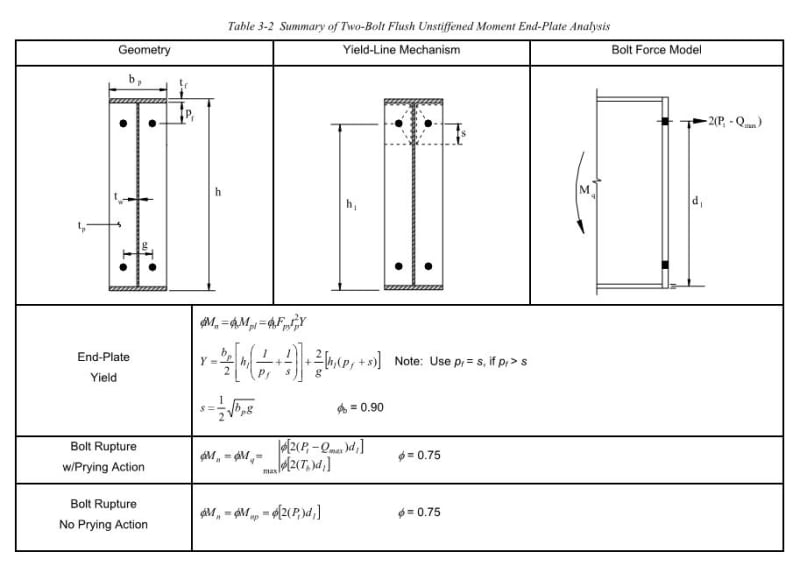
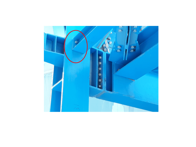
During my visit to a site I have noticed steel connections I am not familiar with ( it is a heavy industry Cement Plant and I have zero experience with this).Would anybody know what type of connection is on the picture? I originally thought it was an end-plate pinned connection but I am not sure as there even isn't a gap between the column and the lower flange of the beam to accommodate rotation. I am not in possession of any calcs so I can't conclude for sure. Has anybody ever come across a connection like this?

Thank you

1_xgyqgw.png
 
Replies continue below

Recommended for you

looks like a simple end plate bolted connection.

Dik
 
Even though there is no gap between the column and lower flange of the beam (the plate goes from top right to the bottom of the beam) I though that for end-plate connections it is a crucial requirement to accommodate rotation of the beam?. Am I wrong??
 
as long as you can accommodate any end moment that might occur.

Dik
 
OP: also, the end plate is thin and would be a fairly flexible connection.

Dik
 
I agree that it is a connection almost certainly intended to be pinned. I would expect it to draw considerable moment if it's carrying transverse load, however, given the proximity of the bolts to the flanges and the relative scale of the member it's tying in to. In my experience, strict adherence to the business of providing connection flexibility at simple connections is a) somewhat recent and b) often ignored in favour of other practical considerations.

I like to debate structural engineering theory -- a lot. If I challenge you on something, know that I'm doing so because I respect your opinion enough to either change it or adopt it.
 

I still dont get how rotation can be allowed for even thou the bottom flange of the beam is butted tightly against the column. Would the concept rely on the rigidity of the flange then???

Another question ,would the same principle apply to that big beam on the picture then?
 
What's not to get? The rotational flexibility of the connection is questionable, just as you've anticipated. I would expect the same logic to apply to the larger beam. To me, that looks as though it was intended to be a shear connection at the end of a short cantilever introduced for erection simplicity.

I like to debate structural engineering theory -- a lot. If I challenge you on something, know that I'm doing so because I respect your opinion enough to either change it or adopt it.
 
The end plate flexes enough to accommodate the rotation at the end. There is some fixity, but, I'd consider it as a pinned connection; depending on the loading, the 4 bolts could become 2.

Dik
 
PeterOdron said:
...I am not sure as there even isn't a gap between the column and the lower flange of the beam to accommodate rotation.

The beam probably does not need to rotate... no gravity (or similar) loading. I believe that beam is a strut, with only axial loading, and is used to brace the column. Notice something a little unusual about that beam. It appears to be "square"... flange width is approximately equal to beam height. This would give the the beam significant Y-axis structural properties... exactly what is needed for axial loading.

Many industrial structures carry heavy loads but don't have the walls and floors of a building to provide bracing. There are lots of beams that don't look like they are doing anything... they are there as column braces, reducing (loaded) beam unbraced length, and bracing truss members.

The larger beam in the photo with an end plate connection could be an axial loaded bracing truss member (this beam appears to be "square", also).

The largest beam, with the six row bolt connection, is the one carrying the heavy load.

[idea]
[r2d2]
 
PeterOdron:
Don’t forget the beam end rotations that we are talking about here are measured in parts of a degree (i.e. the slope of the beam at that location) or a degree or so, not in parts of a 90̊ quadrant or many degrees. That thin end plate does not have to flex very much for this rotation to happen. Then, on the bigger beam, they have gone to great lengths to do CJP welds btwn. the end pls. and the flanges and then grind those joints with a generous radius, so that the two top or bot. flgs. hardly touch. Thus, no forces in those flgs., from moments, could be practically transmitted in any case. Finally, we know very little about what they were really trying to do at that complex connection detail, there is little evidence that that is a good example of good clean design and detailing, we know nothing of the loads, etc., on that framing system. All-in-all, those details might not be something that an inexperienced engineer would want to emulate, although they do look like they were done by inexperienced engineers and detailers.
 
SRE said:
I believe that beam is a strut

Me too. Appears to be part of some kind of horizontal truss.

I like to debate structural engineering theory -- a lot. If I challenge you on something, know that I'm doing so because I respect your opinion enough to either change it or adopt it.
 
I think of it this way. A physical pin may not always the same as a structural pin. In the above it is not a physical pin but a structural pin (no design for moment) just simply connected to a fairly large member with an end plate connection (not designed), overall it increases the stiffness of the structure and also the torsional rigidity of the member and overall a good idea.
 
This isn't a hot button issue for me but I am surprised at the number of folk here who see this is a more of a pin than a fix. I would have expected it to go the other way. The clip below is taken from AISC's design guide on the use of these arrangements for intentionally resisting moment.

c01_pkbvou.jpg


I like to debate structural engineering theory -- a lot. If I challenge you on something, know that I'm doing so because I respect your opinion enough to either change it or adopt it.
 
Looks like a strut. The details do look a little funny, but I can't say I've never had to detail a little funny, too, in order to make something work. My guess is the owner or contractor did not want any field welding and wanted as many shop assembled pieces. There are better ways.

KootK, I agree with you. I think some people believe proper moment connections should be capable of being designed to transfer nearly the entire plastic moment capacity of a beam, and if that's not what they believe, that's simply what they're used to seeing because most moment connections can be configured to do so. That's how most moment connections are configured geometrically. The flush end plate moment connection is not really intended for transferring full plastic moments of a beam into another member, so it just looks a little wimpy. It's just there to transfer the moment in the beam, which isn't its full plastic moment, and I wouldn't expect it to transfer the full moment capacity.
 
If this beam was turned to be vertical, this would be akin to a pinned baseplate connection. I doubt many of you would argue against that.
 
bhiggins said:
I doubt many of you would argue against that.

I don't think that there's anything that gets argued about more frequently here than "is my base plate pinned or fixed". So much so that we should probably have a white paper on it. I don't at all ascribe to the concept that inboard bolts make a connection more of a pin but it's probably best to leave that for another thread.

I like to debate structural engineering theory -- a lot. If I challenge you on something, know that I'm doing so because I respect your opinion enough to either change it or adopt it.
 
Status
Not open for further replies.

Part and Inventory Search

Sponsor