Eng-Tips is the largest engineering community on the Internet

Intelligent Work Forums for Engineering Professionals

Connector Names and Numbers in the Presentation of Small System Interconnects

Status
Not open for further replies.

Eisenhauer

Aerospace
Nov 18, 2022
5
0
0
GB
Just wanted to hear your opinions; there is already fighting about whether connectors are called Js or Ps, plugs or sockets, receptacles or plugs and whether male pin connectors can be receptacles or
female contacts means a Jack or it is a matter of what plugs onto what or what totally covers the other....

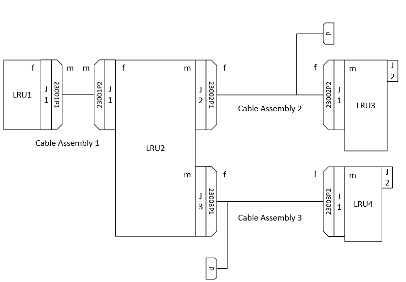
Generally I try to stick with the following convention (see pic):

[ol 1]
[li]LRU connectors have sequential Jn assignments regardless of what gender the pins or whether the manufacturer calls it receptacle or plug.[/li]
[li]All that plugs into the LRU Js are then Ps (loose ends). Also regardless of gender.[/li]
[/ol]

Now with that out of the way how would you go about numbering the mating connectors in the system wiring harness that may comprise several individual cable assys, some ends may have interfaces to the aircraft (meaning in a wiring diagram issued to an installer before they will likely get re-named by them iaw. their own conventions).[/li]

Would you start each cable assembly having its connectors named P1, P2, P3 regardless of where they plug into?
In other words a P1 could plug into a J2 - making some people uncomfortable.
One could also number them (regardless of what assy they belong to) sequentially that there will never be two P1s also causing non-matching numbers to mate.
Also there could be two P1s in the overall system harness but in different cable assys, that will also make some people unhappy.

But from my POV however having each cable assy numbered P1 to Pn is the most logical in a presentation, regardless of which LRU J they plug into.


Any comments? Thanks, Mike

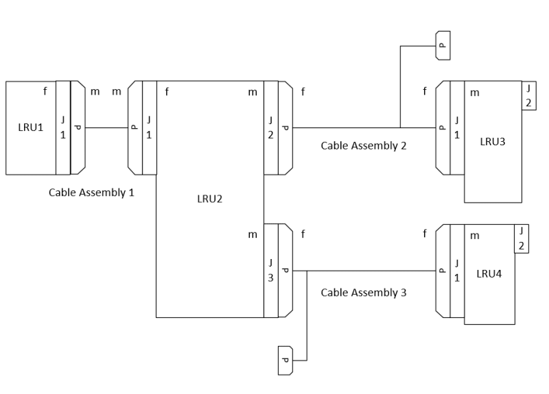
Example small system intentionally showing no P numbering:
Small_Example_System_ycptxm.png
 
Replies continue below

Recommended for you

Would you start each cable assembly having its connectors named P1, P2, P3 regardless of where they plug into?
In other words a P1 could plug into a J2 - making some people uncomfortable.

You're missing a bunch of information that might make your question moot. Give the cables harness numbers, and the connectors reference identifiers based on the ATA code of the systems you're interconnecting. With such unique identifiers in the system, you may feel less compelled to make the connectors at each end of a cable P1 and P2 because all the other prepended numbers will make the connectors unique before you do that. You'll have "24210P1" and "24211P1" which are already unique.

Do you have some OEM wiring diagrams to refer to? There are slight differences but most of them follow the same pattern. Uh... clarification: big differences between US manufacturers and EU manufacturers IIRC, but comparing several US OEM's will yield many similarities.
 
Thanks for your reply Sparweb!
The items in question I am concerned about are all within one system, in this case a communications system. E.g. here we have multiple radios and multiple control units that connect to one another and to other aircraft systems.
Using your example I assume 24210P1 would be 4-digit ATA code, one digit harness ID then Connector ID?
So I use the ATA code within our system interconnect as well and not just for the interface between our system and the aircraft's e.g. audio and power systems?
Also we have no control over what that interface between our system and their system will physically look like, it is not up to us to define this. Therefore it is probably even pointless to give that a connector or 2300 number at all.

Thanks

Mike

Is the below roughly what you propose?

Small_Example_System2_stgtyq.png
 
If you are talking about 14 CFR Part 25 aircraft (transport category, i.e., airliners) each OEM has a standard wiring practices manual that should govern this convention. Sparweb is correct as far as Part 25. I cannot speak to any other aircraft category (Part 23, 27, 29 etc.) but I am sure Sparweb is correct there as well.
 
Sure, Part 21 governs the organization and administration of the design, but Parts 23 and 25 refer to the category of aircraft design itself.
I'm just going to assume you are working on Part 23 aircraft (Cessna/Beech/Pipistrel, etc. etc.) because you are asking these questions in a (seeming) vacuum, which is extraordinarily unlikely if you were designing a system for a Part 25 aircraft (Boeing/Airbus/Bombardier etc).

Your updated diagram is a bit closer to the typical presentation of OEM wiring diagrams, with a few quirks and several large gaps yet to be filled. This diagram only works if the cable harness is already completely fashioned end to end for plug-n-play installation. That's terribly rare. You usually have to pass your harness through some other disconnects for it to fit the aircraft. There are no intermediate disconnects in your diagram. That's a hint you are far away from "prime time" and the solution to this is to go see the aircraft and read its books. Take copies, download PDF's or whatever, and determine how your wiring will integrate into the rest of the aircraft.

Do you have a pin-out definition somewhere? Usually the majority of the time to do the layout consists of drawing all the wires. Having it on a separate harness diagram works, too, but makes troubleshooting harder.

As another point of reference, your work so far looks like "10%" of the job done. Just sayin'.
 
In Commercial Part 121 airline work, I generally see Wiring Diagrams and System Schematics, the purpose of each is defined by some evolution of ATA manual specifications.

Wiring diagrams along with equipment lists and and standard wiring practices manuals provide all the information necessary to repair or replace a conductor.

System schematics really just contain that subset of data necessary for developing a rapid understanding of how the system works, every connection and termination is not shown.

I recommend obtaining the specification for presentation of technical data for the industry sector you are preparing the diagrams for. I'm sure the military also has a preferred format.

In the same environment we also have what I call rework DWGs that graphically describe modifications to existing circuits. I prefer rework DWGs as I believe most techs do because you can just see what is done as opposed to reading paragraph after paragraph (or spreadsheet tables with codes) to see what wiring changes are made changed.

There are also a number of formats for harness fabrication DWGs too.


My posts reflect my personal views and are not in any way endorsed or approved by any organization I'm professionally affiliated with.
 
Thanks for the contributions so far. I think there is still some confusion as to what I am after.
We are providing small systems that will be integrated primarily in helicopters (medium to large) and aircraft, special mission stuff. Generally this is retrofit but sometimes it goes into factory new aircraft. In this case a comms system. We have no control on which platform the system will get installed on, we generally know but it is out of our hands. They buy a capability i.e. black boxes from us with some docs and from thereon do their own stuff. In this case it will be many different types and their variants, can be MIL or CIV. The diagram is provided for the sole purpose that the system installer/fitter e.g. part 23 org reads, interprets and then draws up their own wiring diagram that will be specific to the platform they are working on and will conform to their applicable standards. From that POV I can supply more or less what I want (informal) as long as they can read it, it makes sense and is correct. The demands of the platform regards wiring is generally not known to us and all they want and wanted over the last 25 years was such an interconnect that shows how the boxes are to be wired between one another and what and where are the interfaces to the platform. With that of course go some other interface docs. So far they were totally content on what we had delivered in the past.
So all I wanted to know here is what is the best strategy to name the removable connectors of the harnesses that connect the LRUs; in this case this is essentially only two harnesses: one between CDU1 and 2 and the other one between CDU1 and two radios. Of course they won't care about my names as they will re-name them anyway, so the question applies only to this initially supplied drawing. Here I have implemented Sparweb's method (light grey connectors on the harness between the LRUs and added a gender m/f).
We don’t supply or build the harness either, not even the connectors.

Small_Example_System3_wsc7os.png
 
Some 'other' Fud-4-Thot...

Aircraft OEM drafting standards for electrical wiring interconnect systems.

MIL-HDBK-863 WIRING DATA AND SYSTEM SCHEMATIC DIAGRAMS PREPARATION OF

ASTM F2639 Standard Practice for Design, Alteration, and Certification of Aircraft Electrical Wiring Systems

Regards, Wil Taylor
o Trust - But Verify!
o For those who believe, no proof is required; for those who cannot believe, no proof is possible. [variation, Stuart Chase]
o Unfortunately, in science what You 'believe' is irrelevant. ["Orion", HBA forum]
o Only fools and charlatans know everything and understand everything." -Anton Chekhov
 
That is a huge change in scope from the initial question and it sounds like it doesn't matter at all what you put on your diagram because your customer is going to take your diagram and ignore it and make their own diagram.

At this point I have no idea what your question really is - all I would do is make a list of the vendor CAGE and Part Number for each box and each box connection, the mating number and a wire list to show which connectors and pins were to connected by listing box#, connector maker CAGE, connector part number, and pin numbers. The wire list will include info about twisted pairs, shielding, and correct wire gauge as required. I would expect the boxes have labels next to the connectors - this can be reference information on the connector list.

If your company isn't making the harness or designing the harness then you don't need to make a diagram of the harness.
 
Thank you all for your kind replies.
I think I have sufficient input to proceed in some more educated manner than before.
I don't expect any issues with the submission, it was just a formality that I wanted resolved and clearly there is not just one answer.
I suggest we close this thread.

Mike


Thanks again!
 
Status
Not open for further replies.
Back
Top