Continue to Site

Eng-Tips is the largest engineering community on the Internet

Intelligent Work Forums for Engineering Professionals

  • Congratulations KootK on being selected by the Eng-Tips community for having the most helpful posts in the forums last week. Way to Go!

Contour Modeling Question 7

Status
Not open for further replies.

BrittToolEngineer

Aerospace
Aug 4, 2016
239
Greetings:

I have a vacuum fixture that I am designing and need to put a .125 dia x .09 deep groove around a set of holes in my mandrel in order to place a rubber gasket to seal the vacuum. I do not know how to model this groove in this unique contour. Can anyone give me some ideas on how to accomplish this? I have attached a picture of the mandrel, the holes highlighted are the holes that I need a perimeter groove around.

Thanks in advance for any assistance.

Brent

 
 http://files.engineering.com/getfile.aspx?folder=75423b59-0173-4be1-ac16-6e5aa955a771&file=Contour_Model_Question.png
Replies continue below

Recommended for you

The first thing I'd try:
[ul]
[li]create a sketch in the size/shape you need around the holes[/li]
[li]project the sketch curves to the faces of your model[/li]
[li]use the projected curves to create a tube feature of the appropriate size[/li]
[li]subtract the tube from your model[/li]
[/ul]

This will leave you with a groove that follows the contour of your model, easily updated by editing the sketch.

www.nxjournaling.com
 
Cowski,

I did the project geometry and tube feature. It worked as that feature does. My question now is, when I create that tube, I now have a groove that is .134 wide x .065 deep. I really need the depth to be .134 as well. Can you help me get that result? Would that be a function other than the tube function?

Thanks again, I attached an image of the cross section for an example of what I just performed.

Brent
 
 http://files.engineering.com/getfile.aspx?folder=889db81d-5a9b-4be3-aa9a-a947d8ecd5a0&file=Contour_Model_Question.png
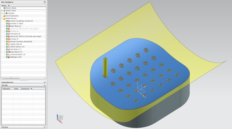
My method would be
[ol 1]
[li]Extrude cylinders for each o-ring gland,[/li]
[li]Offset the tool surface to the depth of the oring gland[/li]
[li]Trim the cylinders with the offset surface[/li]
[li]Apply suitable edge blends to the cylinders[/li]
[li]subtract cylinders from base body[/li]
[/ol]
o-ring_glands_trim_nx11_ljt9jk.png


I have included a NX11 file.
 
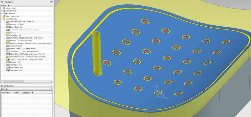
Ahh misunderstood, it helps to read a bit more carefully, but never-mind the same method should work for a perimeter gasket.

gasket_nx11_m4lj32.png
 
Alternative 1: you can create the cross section that you need then use "swept" or "sweep along guide", using the projected curves as the guide string.

Alternative 2: edit your sketch to create the inside/outside perimeter of your desired groove, extrude the sketch toward your part, use "trim body" to trim the extrude back to the face(s), use "offset face" on the trimmed extrude to create the groove depth, subtract the extrude from your part, and finally blend the corners of the resulting rectangular groove to round it out.

Edit: didn't see petulf's post until after I posted, alternative 2 is similar to petulf's suggestion, but on a larger scale.

www.nxjournaling.com
 
Here's how I blindly went about it....some different methods of getting same results.

vaccuum_block_nx9.zip

Tim Flater
NX Designer
NX 9.0.2.5 Win7 Enterprise x64 SP1
Intel Core i7 2.5GHz 16GB RAM
4GB NVIDIA Quadro K3100M
 
A simple Extrusion will not work on curved surfaces. To get a more or less constant depth it must follow the surface normal.
If the groove width could be double of the depth you could use the tube Feature, otherwise a variatonal sweep will do the job.


 http://files.engineering.com/getfile.aspx?folder=a6fcc2c3-fb7f-4c6d-8673-20e93e5f60ff&file=vacuum_block_md.zip
t300master said:
A simple Extrusion will not work on curved surfaces. To get a more or less constant depth it must follow the surface normal.
If the groove width could be double of the depth you could use the tube Feature, otherwise a variatonal sweep will do the job.

No one suggested using a simple extrude by itself. The "offset and trim" approach results in a surface that follows the original. The variational sweep is overkill in this case, but could also work.

www.nxjournaling.com
 
Can you post the file in NX 10 or 9? I don't have NX 11 up and running yet.

Based on your screenshot, I suspect that you are measuring along the extrude direction vector rather than the surface normal vector; if this is the case, the measurement will vary depending on the difference of the angles. Should you measure along the surface normal, you will find the depth to be a constant value that was specified in the offset (within modeling tolerances, of course).
www.nxjournaling.com
 
t300master is correct, variational sweep is definitely the way to go for longer grooves as it is accurate and gives the most control over the profile.

Anyways worked a bit more on the part, mainly to try out variational sweep and the difference between o-rings extruded along the o-ring's center surface normal, variational sweep and o-rings created by thicken which should give sidewalls such that the sidewalls always follow the surface normal.

glands_orings_v2.png


The part file is included in NX9 format.


petulf said:
should give sidewalls such that the sidewalls always follow the surface normal.

petulf,
I think you found the point of contention between my answer and t300master's. I work mainly on injection molded parts where the side walls of a groove need draft in the pull direction. It is not desirable, in my situation, to keep the side walls normal to the surface. If this is a requirement, then I agree that variational sweep is good way to do it ("thicken" would probably be easier to set up and maintain). However, I maintain that the extrude and offset method will give a constant depth groove when measured from the full original face to groove face (not along the sidewall).

www.nxjournaling.com
 
Yes I agree, also the variational sweep (at least as I modeled it) will only follow the surface normal along the path curve, which means that there is an error in depth towards the sidewalls. Thought this could easily enough be corrected by trimming with an offset surface as in the extruded/tube example.
 
Hello

sorry for my late reply, buat I've been out of Office.

Of course the Offset surface gives a constant depth groove measured against the original surface. But you can't mill this groove.

And when it comes to production there will be a difference between the variational sweep and a milled groove.
Also it is not equal if you uses the top or bottom face to create a path curve.

One interesting point is that the selection order of the faces for creating the section curves "path bottom of groove" has an influence on the path normal.
You need to select the curved surface first, then the cylinder.

my very best regards

Meinolf
 
 http://files.engineering.com/getfile.aspx?folder=d608992c-52a9-491c-921e-7edc10943e61&file=groove.prt
Status
Not open for further replies.

Part and Inventory Search

Sponsor