Eng-Tips is the largest engineering community on the Internet

Intelligent Work Forums for Engineering Professionals

Control Help 1

Status
Not open for further replies.

jaytelle

Civil/Environmental
Dec 15, 2021
23
0
0
US
Hello,

I'm an environmental engineer and trying to put together a filter prototype. My ignorance on electrical/controls is monumental. Assume nothing I say is correct.

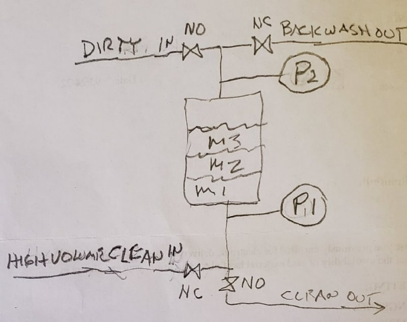
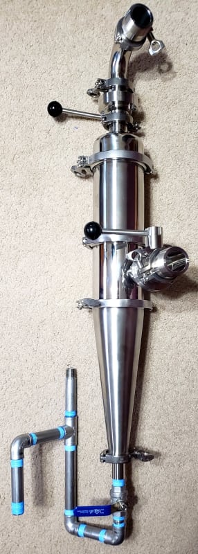
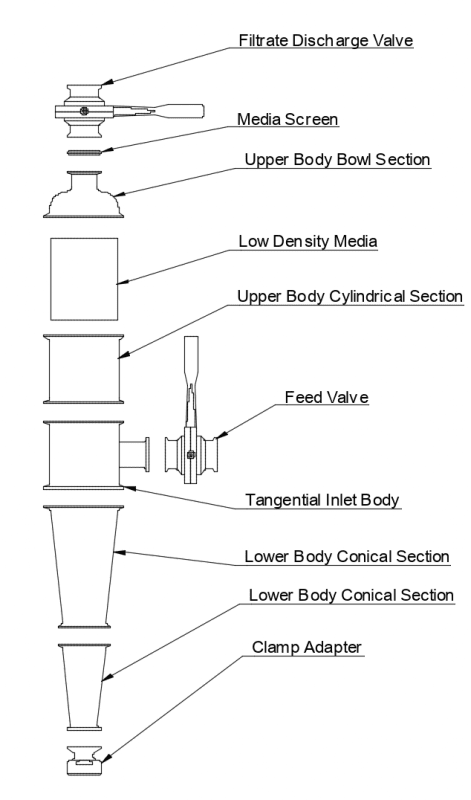
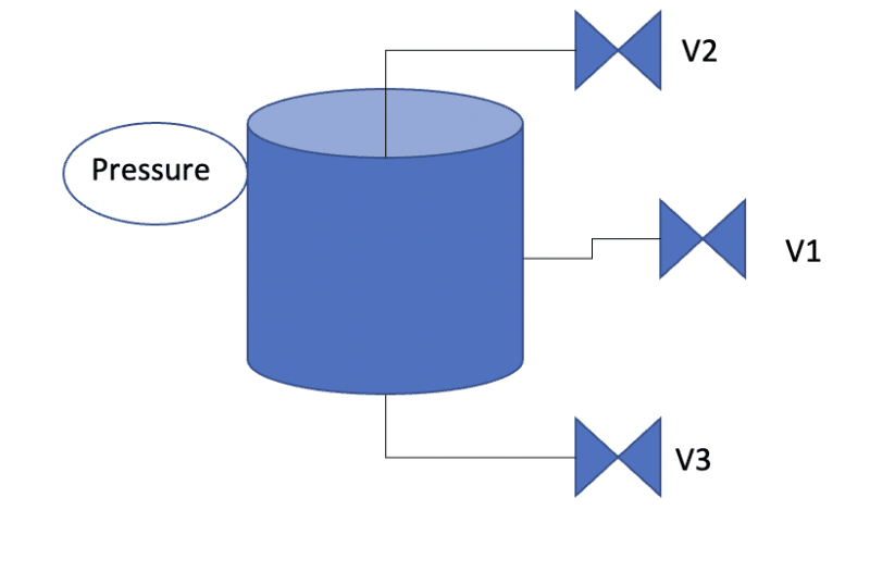
So basically this is a media bed filter - I attached some images below. There are three motorized ball valves: 1 is a feed valve, 1 is a drain valve, 1 is a filtrate/backwash valve. Below is a brief description.

1) Normal operation, flow goes through V1 and out V2. V3 is closed.
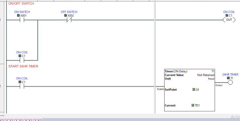
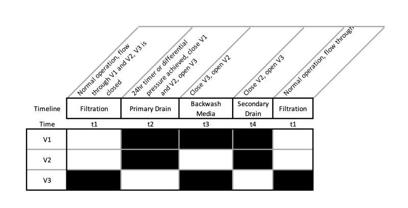
2) If the pressure switch is triggered or an external 24hr timer expires then the unit does an auto clean
If pressure switch was triggered, it resets 24hr timer​
V1 and V2 close (V3 normally closed)​
V3 opens to drain the unit (V1 and V2 are closed)​
V3 closes (V1 and V2 are closed)​
V2 opens to backwash media (V1 and V3 are closed​
V2 closes (V1 and V3 are closed)​
V3 opens to drain the unit (V1 and V2 are closed)​
V3 closes (V1 and V2 are closed)​
V1 and V2 open (V3 closed)​
3)Return to step 1

My questions are: Is this possible to do with simple timers( I imagine that each of the Qty 8 steps requires a separate timer? Plus Qty 1 24hr timer. Total of 9 timers?

Does this make any sense? Is there a better way for someone who has no control experience to get this done?

Many thanks,


Screen_Shot_2022-04-22_at_6.17.42_PM_lhwrxh.png
Screen_Shot_2022-04-22_at_6.18.02_PM_czcoyi.png


JL
 
Replies continue below

Recommended for you

Yes, this could be done with relay logic, a combination of the pressure switch, timers and relays. But your situation screams for a low level PLC (programmable logic controller), it's exactly for what the PLC was invented for.

PLC self-teach lessons here: Link among others I'm sure.

The advantage of a PLC is that when you fire it up and it doesn't do what you expected and you finally realize what the problem is, the PLC can be re-programmed for changes (as many times as needed), without re-wiring or changing or adding timers.

Lots of advice on PLCs.net forum, too (it's a site dedicated to PLCs).
 
Thanks for the response danw2.

I was actually looking into PLC before I started thinking about timers. I have some issues though...mainly I run a Mac system and can't find any economic PLC programming options that run on Mac. I was initially thinking of using the click plc as I don't need a lot of I/O to run and they are cheap, but the programming software doesn't work with Mac OS.

Thank you

JL
 
I do media filter controllers about twice a year and sincerely hope your plumbing is NOT like the drawing above.

After trying many different methods of controls I finally landed on Clicks and they've been the most logical. Combine one with a 4" touch screen and it's the bomb for water filters. Macs be damned..

You should find or buy a cheap old laptop running windoz and go with the CLICKs.
You can also run a windows emulator on a Mac to run Mac programs. I've not tried using the Click SW that way. I'm not sure how it would work since it's a communications based piece of software. Though, if you use an Ethernet based Click that would probably work fine.

You can use timers but it quickly gets out of hand er, mind while you struggle to keep all the contingencies straight. Then you decide you need an extra backwash and you're screwed. Or worse, something goes wrong in a year and you have to try to figure out what and how it all works again -miserable!

The normal way you run a media filter is:
FILTERING: water in at the top down thru the media out the bottom.
BACKWASHING: water in at the bottom at (typically) three times the filtering flow rate out at the top to be discharged to waste.

This requires at minimum and depending on the rest of your "plant" three valves, often four and at least one rate control valve.

With no valves energized the water should flow as stated in FILTERING via Normally Open Valve(s).
When a BACKWASH occurs those valve(s) should be energized to close it/them and another Normally Closed Valve is energized to OPEN. This prevents the constant waste of power the entire time filtering is occurring which is normally 95% or more of the time.

Normally OPEN N.O. valves can be hard to find sometimes but Ebay motorized ball valves are better, cheaper, more reliable, and fit the bill as it doesn't matter since they'll essentially Normally BOTH way since they self-disconnect as soon as they reach fully OPEN or CLOSED.

You need two pressure transducers to do differential control unless you buy a differential pressure sensor OR the filtered output is a fixed head. A fixed head is only a setup where the filtered water pukes into an atmospheric tank at the top so the output pressure is calculable and absolutely constant. Then you can use a single standard pressure sensor to only monitor the dirty-in pressure at the filter.

..continued

Keith Cress
kcress -
 
Media_FIlter_EngTips_cgjxjp.jpg


You also need a rate control valve in the backwash source supply to set the backwash rate.

You manually set that rate by doing a backwash and cranking up the rate until media starts getting carried out the waste dump. That is the maximum bed flotation that will remove the filtered junk most thoroughly. Of course you do NOT want your media leaving so you throttle down a bit more to the point no media is leaving at all.

In a fully valve operated system (which I totally prefer) you close the Filtered Out and The Dirty In valves and then open the Waste Out and Clean Backwash Source In. Since the Filter IN and Clean Out are NC and the other two are NO you can actually use a single timer to run it all since you energize all valves to BWash and no valves to Filter.

A PLC would be a much better route if you do anything beyond Filter and BW. Running a well pump, chlorinating, having to also run a Rinse in a drinking water system. Counting washes, monitoring turbidity, iron removal, arsenic removal, water softening, etc., etc.

Keith Cress
kcress -
 
itsmoked...thank you for your responses.

After paying for 'parallels'..then paying for windows 10..I finally was able to get the click software on my mac. Now I just have to learn how to do the ladder logic part. I did purchase a click PLC and power supply, so I will be in my garage for the foreseeable future learning how to use it.

This is not a 'typical' media filter. This is a packed bed cyclonic filter using low density media - something I recently filed a patent for. See image. The feed is below the media and generates cyclone which helps keep the media bed free of solids. The backwash is basically just to jar/agitate media so any trapped particulate sloughs off. There is an anti-siphon on the bottom to prevent the media from being discharged during the drain phase.


UNIT-M-030-WOP_ipk8mp.jpg


Screen_Shot_2022-04-24_at_12.01.12_PM_kyen7h.png
Screen_Shot_2022-04-20_at_1.31.18_PM_pfrmjc.png


JL
 
Ah.. Interesting.

Is that filter for a specific application?

Glad you got the CLICK Programming SW going on your Mac. I knew you could do it!
Are you talking to the CLICK via Ethernet or serial?

For product development I think you made the right move to use a PLC.

Make sure you figure out how to COMMENT the rungs as that is a huge help with working the programming. Definitely make use of the easy color settings. For instance comment in red if it's something that needs removal after testing or is temporary,etc. That's such a key feature of CLICK that I've literally dumped other PLC models with only rudimentary commenting abilities! Several other ADirect PLCs have horrid abilities in that regard, like five clicks to change the color and then in horror it changes ALL comments to that color. Shesh.

You should consider the 4" HMI touch panel to go with your PLC.

Very easy to use, free good SW. It would easily allow you to see any parameter and to change any parameter without a PC involved. You could change filter times, force backwashes, see pressures, graphically display deltas etc. I see it's back ordered but AD is very conservative with their expected dates. I ordered a 10" EA9 panel that was predicted out 30 days and got it in two days.

Keith Cress
kcress -
 
The filter does not have any specific application limitations. It is meant to be used in systems where a traditional media filter or cyclone separator or bag filter are used. Of course certain applicstions are better than others. The image attached is a 4" body unit and can do about 30gpm. Primary market would be cooling tower filtration.

Another great Mac M1 feature...no standard usb or ethernet port. I have a converter from usb-c to rs232 to rj12.

Do you have any reference material you can suggest for a guy who has no plc ladder logic experience?

JL
 
Gads on the comms, amazing it works.

Do you have any reference material you can suggest for a guy who has no plc ladder logic experience?

Not really.

With the CLICKs it's pretty straight forward. There are all sorts of methods for how you should code PLC ladder logic. I've read most but with a few exceptions do it my own way. This wouldn't be acceptable if anyone else would be expected to maintain my code. In a company you MUST have a style that everyone adheres to.

When you get your CLICK hook it up and mess with it. You can't hurt it. You can hurt things controlled with it but since CLICK nicely has LED indicators for inputs and outputs you can see what's happening. Hook a few outputs to a few inputs and mess with the code. Only about 20 commands of which you typically only use about 10 of in programs.

With regards to PLC Ladder Logic execution there are a few things to keep in mind.
The "last rung wins"! You can have all sorts of clever logic running a variable but if there's a later rung affecting that variable it wins and is the final result.

A PLC reads all inputs.
Using the outputs from last rung scan it then
Runs all the logic starting from the first rung thru to the last rung.
Updates the physical outputs.

ALWAYS.

Mess with the timers until you understand them. Each function has a help on it that's very useful and usually good enough. I refer to them often to remind me of the function's details.

I recommend you go to the bother of putting a comment rung in at the beginning that states exactly what the program does in a clear manner. When you REV the code put in a date and a REV line at the end of this first comment. If your notes get too long add another comment rung. I've gotten clear to 4 comment rungs which is a whole lot in CLICK land. Probably 2 pages of text. Color things that need highlighting like functions to be added later.

Comment every line or group of lines if the function is a couple of rungs. This is very important when you come back in month to make a change.

I recommend you run a separator comment rung across the bottom of your logic with it marked
------------ OUTPUT ---------

And make this the only place you put outputs that should make it out of the PLC into the field.

It's very BAD form to have any outputs buried in the logic rungs. It can be disastrous.

Outputs are "COILS" from history. You use the "C" type coils for all outputs inside the logic area above --OUTPUT--
then in --OUTPUT-- you simply assign them to the correct "Y" output which actually manipulates the physical outputs.

Often you can string simple conditionals in-Rung here to block outputs. This is very useful in troubleshooting because you can "WATCH" the live execution and scroll down to the ---OUTPUT--- section and instantly see what's blocking an expected output that's mysteriously not coming on.

So, up in the logic you can have a bunch of complex logic feeding , say, a timer or counter that ultimately has to reach some stage before an output should activate. That timer's output would be put done in ---OUTPUT--- in the rung to the physical output. A glance would show where the BLOCK is happening.

Name your variables as descriptively as you possibly can to minimize as much as humanly possible the abstraction as abstraction is NOT helpful in ladder logic. However, keeping the "C" coil admonition above where an output is realized in the logic but must me expressed down in ---OUTPUT--- you can name the "C" version something like "cBackWash Output VLV" then down in ---OUTPUT--- you have:

Code:
-------------- OUTPUT ----------------------

cBackWash Output VLV                 BackWash Output VLV
        C25                                   Y6
--------| |----------------------------------| |----------


Where the "c" is dumped in the actual output rung.

Now give it a try.


Keith Cress
kcress -
 
it smoked...thank you again for your response.

I am learning, I think. At least I have my click (they overnight shipped!)

Screen_Shot_2022-04-27_at_4.21.33_PM_fqg9jg.png


I have a question that I'm confusing myself on... if the PLC goes rung by rung don't I need to have the outputs in order? For example if the order of the valves closing/opening matters, doesn't the coil output (Y) have to be inserted into the rungs and not at the end of the ladder logic? How is it possible to have all the outputs at the end if the sequence matters? I know it's possible as you told me, but how do I make sense of that? I'm not sure I'm making a whole lot of sense.

JL
 
It can't matter really because as I stated the PLC does not actually update any physical outputs until everything else has been done. So if you poorly scattered "Y's" throughout your code they ALL would get physically updated at the same instant. The PLC not only updates the outputs last it updates them simultaneously.

This matters not to the valves because it's so fast. You'd be changing the actual valve positions all at once between filtering and backwashing.

The PLC executes super fast so your outputs are being controlled by timers for backwashing and filtering which last minutes.

Those timers or pressure readings are what are controlling the outputs and the order in which they operate NOT their order in the rungs.

Setup your PLC program without any physical outputs. Run it strictly on time. Use seconds for debug and learning. And watch the Filter and Backwash cycles on the LEDs of the outputs.

Keith Cress
kcress -
 
Status
Not open for further replies.
Back
Top