Continue to Site

Eng-Tips is the largest engineering community on the Internet

Intelligent Work Forums for Engineering Professionals

  • Congratulations KootK on being selected by the Eng-Tips community for having the most helpful posts in the forums last week. Way to Go!

Control room above 66 kV GIS Building 3

Status
Not open for further replies.

Power0020

Electrical
Jun 11, 2014
303
The space available is very tight with a new plot for a 220/66 kV substation.

to the best of my knowledge, I have never seen a control room above a 66 kV or more GIS room.

I don't think there is any electrical reason for that.

I doubt it is mostly due to structural loading of the roof with GIS rooms usually having a wide column-free span.

Any clues?
 
Replies continue below

Recommended for you

Hi Power,
I don't believe there to be a technical reason why you could not design a control room above a GIS switch-room. It would not be my first choice, but you can engineer your way out of a lot of not-my-first-choice situations, it always comes down to $$.
The building would need to be able to support the control room, as well as meet all applicable codes for; number of occupants, fire, egress, seismic, (other risks?), etc.
Good luck and let us know how it turns out.
Regards,
GG


"I have not failed. I've just found 10,000 ways that won't work." Thomas Alva Edison (1847-1931)

 
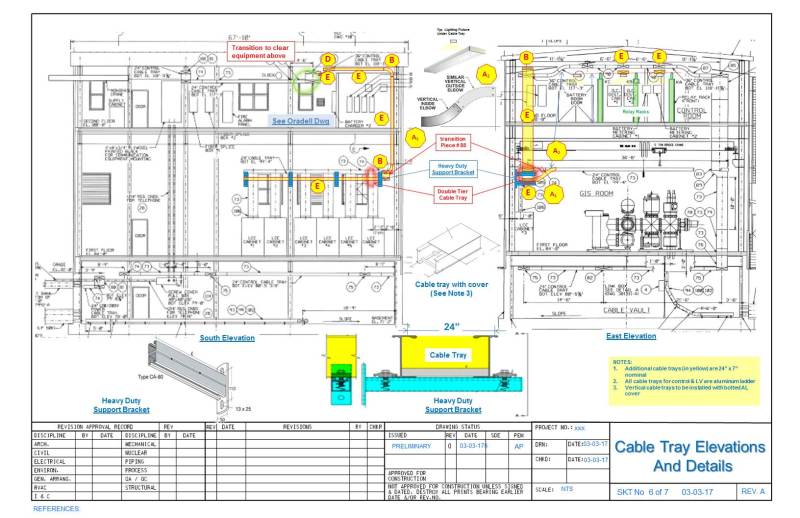
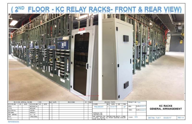
We completed 15 GIS substation projects in a urban congested areas with control rooms above the GIS deck. See below for more details.
GIS_Bldg_Elevation_P_C_-_Dumont_acp04p.jpg

2nd_floor_P_C_-_Dumont_cd2jvm.jpg
 
I commissioned a two station, eight breaker ring bus per station in an urban area 15 years ago. All of the relay panels/controls were on the top (fourth) floor. The transformers were in the basement. The last thing constructed was the actual stairs. For several months I was climbing scaffolding stairs to get up to the top. Due to the location in a major US city, that $$ compromise was made. The GIS itself was 3 levels high. In this location, the top floor may have offered additional physical security.
 
It very common in INDIA to have the indoor GIS stations with the control room on the top floor in urban areas.Space constraint is the main reason for opting to the GIS and hence there is no other way.
I wish to share the points on the grounding of the GIS substations .Hello Mr.cucky2000 can you throw some light on this?
 
Typically the ground grid areas available have limited space causing potential saturation and localized hotspots exceeding the allowable step and touch potentials. A general recommendation could be divided for the following:

1) External Yard Ground grid: Use deep rods if feasible and take advantage of ground foundations and concrete slabs as a supplementary ground electrode. Diagonal ground conductors (counterpoise) could also help to reduce hotspots.

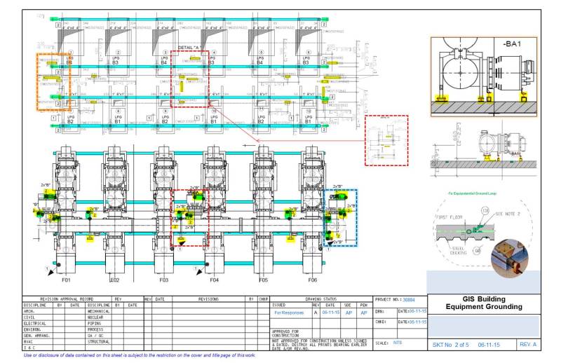
2) Internal Building ground: Ground the floor steel rebar to form a quasi-equipotential surface. If there is concern with steel magnetic saturation, consider the use of copper ground loops 20'x20' (~6mx~6m) to avoid high frequency magnetization caused by very-fast transient wave notorious on GIS of single bus per phase typically on design 220 kV & above. (Less severe are for GIS with 3 phase in a single tube typ. On design up to 170 kV).

For grounding detail, see below couple sketches that we hope bring some light to your questions.
GIS_Grounding_1_d7hnnh.jpg

Grounding_2_njzocj.jpg
 
Cuky2000, while I am not currently involved with anything GIS, I can say your post is worth the gold. :)

BTW, forgive me, but what do you guys mean by "hot spots"?
 
Hi Mbrooke: Thanks for your kind words.

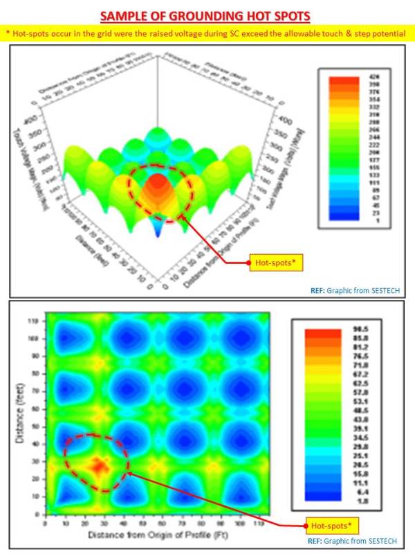
"Hot-spots" terminology is used by some engineers to associate unsafe dangerous zones on the substation represented by red areas in typical step and touch potentials grid plots similar to the one shown below.

This method can be visually identified and help quickly to refine grounding designs.

Hospot_Sample_-_Grounding_Plots_xb2vfk.jpg
 
Just to add to the great stuff by cuky2000 about the hotsopts that it should be coordinated with the layout to see if the peak points are reachable or not.

i.e. a typical touch voltage involved an extended arm (maximum 2 m ) within reach, so the 3D voltage mesh should be "touch voltage" not only "GRP absolute values".

This is true for outdoor substations.

Another subject here for GIS stations: some local standards ask for epoxy coated rebars to be embedded in GIS hall concrete slab, the coating galvanically isolates the rebars from concrete and electrical contiuity of rebars are not clear.

The coating has a breakdown voltage of around 5 kV.

The steel rebars are NOT part of earthing grid, and induced voltages may arise during VFTO, I personally think these rebars are electrically "useless" as it can't be considered equi-potential.
 
Power0020: Thanks for your observations on the steel rebar issues for grounding application.
If there is no code constraints using conductive rebar, there is way to simplify the floor grounding design adding a dimly cooper loop to minimize the effect of the high frequency VFTO.
See the sketch above for a conceptual application.
 
Status
Not open for further replies.

Part and Inventory Search

Sponsor