Eng-Tips is the largest engineering community on the Internet

Intelligent Work Forums for Engineering Professionals

Control Valve Bypass Arrangement 2

Status
Not open for further replies.

DGrayPPD

Mechanical
Feb 2, 2017
300
0
0
US
Good morning everyone,

Just had a quick question. It is pretty basic, but I would still like the opinions of some of the experts on here.

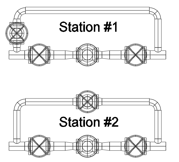
Please refer to the image below. I have given two examples of a control valve station from a plan view. Station #1 would seem to allow easier access to the bypass handwheel and it reduces cuts and welds which saves $$$. Station #2 however shows a more balanced, even arrangement between the bypass and control valve.

My question is, which do you feel is the more ideal arrangement? Is there a benefit to having the bypass even with the control valve in Station #2? If so, what is it? I know what my opinion is, but it is always nice to have validation or for someone to give you legitimate reasons why you may be wrong.

Thanks for the tips.

Capture_zfawnu.png
 
Replies continue below

Recommended for you

I agree. After hearing your, honestly, quite obvious logic I have changed my thinking. Not sure why I haven't thought of that before. When the scenario comes across my desk down the road I will try to state my case and see what happens.

Thanks for the help.
 
LittleInch is singing from my hymnbook.

A bypass is a dangerous replacement for an installed spare control valve where one might actually be needed. The only time the bypass can be left accessible is if the control valve itself is not really necessary. Only then will it pass a properly conducted Hazop.

Sure, you can take the handle off or lock it out so it's used only for maintenance- some people are good with that, if the valve is used for convenience during maintenance. But the idea that somebody is going to be standing by that valve, which is likely massively over-sized relative to the control valve, changing its position based on what someone is telling them over the radio from the control room...seriously? If you operate your plants like that, ever, you're just waiting to have an accident.
 
...and if you're only asking the simpler question: both A and B are less than optimal. The optimal arrangement doesn't trap the control valve in a segment of line that can't easily be drained and which may collect sediment or debris. It also has a "trombone piece", i.e. a U shaped piece of pipe with a flange at each end- which can be removed and taken right out of the way, rather than trying to pry hot flanges apart from one another on a live line in order to make space between them to remove the (flanged) control valve from the line. But you do the best with these you can.

B is just an attempt to make the pipe look like the symbols on the P&ID, which is what people usually do if they don't know any better.

That trombone piece detail is especially important if the control valve is installed with something which is not "zero clearance" for removal, which raised or flat-face flanges are (at least in theory). If you're using RTJ flanges, compression fittings on rigid tubing, Victaulic roll-grooved piping etc., you really do want the trombone piece.
 
Status
Not open for further replies.
Back
Top