Continue to Site

Eng-Tips is the largest engineering community on the Internet

Intelligent Work Forums for Engineering Professionals

  • Congratulations waross on being selected by the Eng-Tips community for having the most helpful posts in the forums last week. Way to Go!

Controlling Feature Location Between Hole Pattern Datum 1

Status
Not open for further replies.

Preston.

Mechanical
May 19, 2021
5
US
Hello All,

I'm new to the forums and have been slowly learning GD&T on the job.

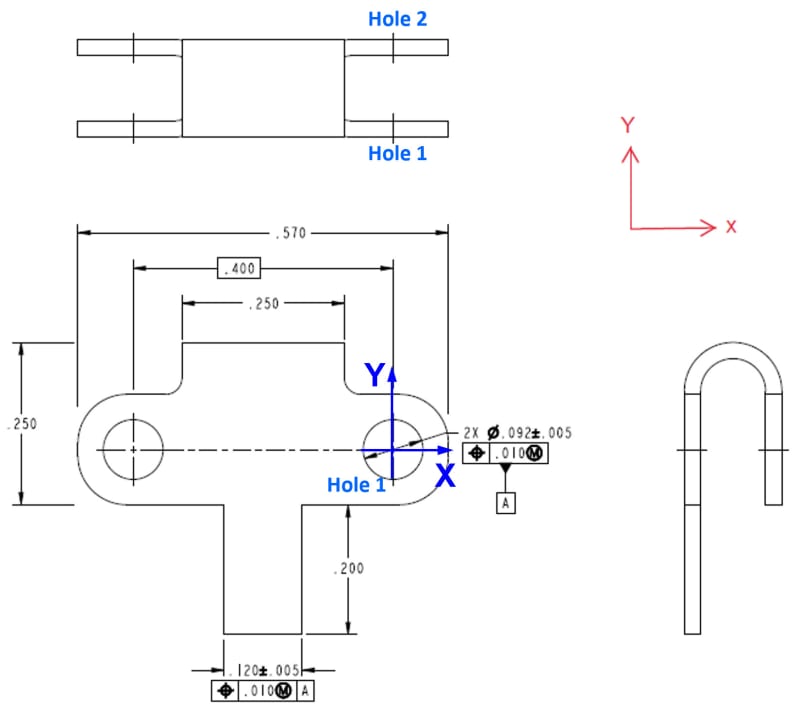
I've attached a simplified example of the part I'm working on. (PLEASE NOTE this is just an example so the part is not fully defined but I think it should serve its purpose for the discussion)

The part is sheet metal and is functionally constrained by the two .092" holes (the part is free to move in the Z direction). Neither hole is more important than the other. Therefore, I have made the hole pattern the primary datum and have controlled the relative location of the two holes with the .010" TP.

I am also trying to control the location of the .200" long tab by using TP w.r.t. the hole pattern datum A.

2 Questions:
1. Is it legal to use TP on .092" holes with no datum reference? - The intent is to control the relative location of the two holes.
2. Is it legal to control the location of the tab using TP? - The intent is to center the tab between the two holes that locate the part.

Thanks for the help!
 
 https://files.engineering.com/getfile.aspx?folder=55511095-ed2d-4133-92c9-36a4fa6612f6&file=Example_Print_Rev1.PNG
Replies continue below

Recommended for you

Hi, Preston:

It is legal to use TP on .092" holes pattern with no datum reference. The TP applies to each other. You do need to add a diameter symbol to this TP tolerance though.

It is perfect OK to control location of the tab using TP. If I were you, I would add a vertical center line.

A main issue with your setup is that you don't have a primary datum feature. I would use the large flat face as datum feature A and use the pattern of holes as a secondary datum feature B. Without the datum feature A (large flat surface), your part can't be positioned properly. If you close your eyes and think, you will "see" that your part is floating.

Best regards,

Alex

 
My understanding on datum feature A callout |POS|Ø.010(M)| (without any datum feature reference) is an implied self-datum coaxial holes, that means datum feature A axis established from the axes of two coaxial features, so I will think there is a hole 2 as shown on the rear side of the part, and I will assume this is not your intended DRF.
Fig. 7-16 (2018 version) is an example of coaxial features callout without any datum feature reference.
Please correct me if I am wrong here.
2021-05-20_091702_ugblmi.jpg

Season
 
Preston,

You need to be clearer. On a sheet metal part, four holes will be punched, and then the part will be bent. The top two holes will have a position error with respect to your datum holes. You are missing a datum.

If this were my drawing, the face on your bottom left view would be datum feature[ ]A. The hole pattern on the bottom face would be [box][⌖][/box][box][⌀].010[/box][box]A[/box], and it would be datum feature[ ]B.

I would have an opposite view showing the top holes with all tolerances including position. Sheet metal bending tolerance are typically around [±].015", so you have a problem. You can slot the top two holes. You can make the bottom holes oversized, and call up the datum at MMC. Tolerancing is not a drafting problem. It is a design problem.

--
JHG
 
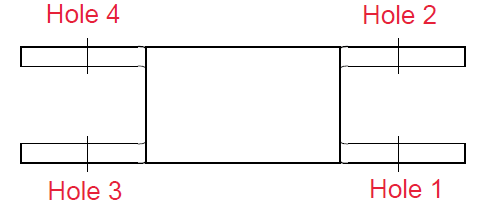
First: I gave the holes numbers so we can reference them (thanks for the idea SeaonLee).
Hole_Numbering_adoxad.png

SeasonLee,

My intent was having holes 1 and 3 as datum feature A. I can see how one could interpret the drawing as you have shown, using holes 1 and 2 as the datum. I would argue the later interpretation is incorrect based on 2 things:
1. The "2X" before the Ø.092" on hole 1 is used to reference the number of times the dimension is applicable within an given view. So it is not referencing hole 2.
2. The examples from Y14.5 have both diameters shown within the same view (such as your example: Fig 7-18 from 2018 standard).

I may be incorrect here so please let me know if I am!

drawhoh,

Good points. I agree with you and jassco: the front face should be a datum feature. Given the part is functionally located by the 4 holes, should that make the front face a secondary/tertiary datum?

Regarding positional tolerances between the coaxial holes (1-2, and 3-4): our supplier has been making a very similar part for 10+ years with no issues. Now, this supplier may be the exception and not the rule, so ±.015" may be completely reasonable in normal circumstances. I'm just not worried about this one.

drawoh said:
I would have an opposite view showing the top holes with all tolerances including position.
This is a reasonable option for controlling holes 2 and 4. Does it matter that functionally all 4 holes have equal importance? Is there a way to give all 4 holes equal weight?
 
Preston

I can fully understand your intent-using hole 1 and hole 3 as datum feature A, but you made a coaxial feature callout.

Season
 
To be fair - it's an ambiguous callout.

Also of interest, given the views the only way to suspect co-axial holes is the not-required axes in the top and side views.
 
SeasonLee,

I was under the impression that I wasn't making a coaxial feature callout based on the two reasons I listed. Mainly that the TP applies to the "2X Ø.092±.005" dimension, which are holes 1 and 3. In order for it to be a coaxial callout, the coaxial diameters would need to be in the same view (similar to the examples from Y14.5).

However, given the confusion, there must be a better way to make the callout. I thought I was doing it to the letter of the law, but maybe not?

3DDave said:
Also of interest, given the views the only way to suspect co-axial holes is the not-required axes in the top view.
What do you mean by "not-required" axes? As in undefined?
 
There was another, unrelated discussion that suggested that nearly no axes would need to be shown unless it was to show related dimensions. Someone thought it was a burden to show other axes.

The callout could just as easily apply to the two inline holes as to the holes separated by a basic dimension - you made an example that could just as easily have omitted the 180 degree bend and with it the extra holes, eliminating coaxial holes as a possibility. You might just as easily have left on the basic dimension accidentally.
 
3DDave,

Ah, so you're saying if I left the axes off the holes in the top and right view, then there would be less confusion. I always assumed it was standard to mark holes with an axis. I don't think it creates some sort of new requirement, does it?

3DDave said:
you made an example that could just as easily have omitted the 180 degree bend and with it the extra holes, eliminating coaxial holes as a possibility. You might just as easily have left on the basic dimension accidentally.
Right, but given the coaxial holes are part of the actual design and the basic dimension wasn't an accident: is the current drawing actually ambiguous, or is there a correct way to interpret it?
 
If there are four holes you could have used 4X and apply the geometric characteristic/FCF and the datum feature symbol would apply to all four, or could have used 4X to define the diameters and added a note to the datum feature symbol "TWO HOLES MARKED "A" " and then put leaders to the two holes with the letter A.

The confusion is that you want to use the two holes to locate the tab, for which the other holes added a confounding element.
 
3DDave,

That makes a lot of sense. Thanks for clarifying!

I always thought you could only refer to dimensions within the same view. i.e. using "4X" in the bottom left view is incorrect because there are only 2 holes in that view. But it sounds like that's not the case. What is the rule for using 2X, 4X, etc. then?
 
The more clear the better. This particular problem is part of the push for model-based definition where no "2X," et al is ever used. Instead the FCF will contain a list of the surfaces it is applied to and the datum symbol (well, there really doesn't need to be a symbol but for user interaction) contains a separate list of the surfaces that comprise it.

I recall the time a checker marked up a drawing of a section through a counterbore as needing 2X in front of fillet radius, because there they were one on the right and one on the left - even though they were the exact same fillet around the bottom. Clarity is always a problem for drawings and adding more views and sections to disambiguate is the best defense, but then people complain it's too much work or they have trouble fusing all the various views and sections.
 
Preston.,

I am guessing that at least one of your flat faces are clamped to something. One of those faces ought to be your primary datum, unless I am guessing wrong.

Your tolerances ought to based on functionality. What is more important to you, the position of hole[ ]2 and hole[ ]4 with respect to each other, or their individual positions with respect to hole[ ]1 and hole[ ]3? This affects your specification.

Your fabricator has the option of not punching the holes, bending the part, then drilling two holes afterwards. This approach is very much more expensive than punching everything.

--
JHG
 
hi Preston

I would make the centreline of the 0.4 hole centres the datum and put a symmetrical tolerance on the 0.12 feature relative to the datum, this would ensure the feature was positioned between the hole centres to the accuracy you require.

“Do not worry about your problems with mathematics, I assure you mine are far greater.” Albert Einstein
 
Status
Not open for further replies.

Part and Inventory Search

Sponsor

Top