Eng-Tips is the largest engineering community on the Internet

Intelligent Work Forums for Engineering Professionals

Controlling "sharp" edges through geometrical controls 1

Status
Not open for further replies.

semiond

Mechanical
Jan 9, 2011
176
0
0
IL
Searching the forum for information regarding application of GD&T on edges, i found thread1103-310372, where it seems that most participants agreed that edges (including those that connect surfaces at an angle smaller than 90 deg.) can legally be used as datums (recommended or not - is a separate question).

In relation to ASME Y14.5 2009, my question is: could the two edges which the OP of that thread intended to assign as datums, be controlled for orientation between each other by the use of perpendicularity control? If i was asked this question my answer would be "probably not" because the definitions in chapter 6 seem to only mention a surface, center plane, or an axis as the subjects for orientation controls. On the other hand, maybe the fact that it's not mentioned in the definitions, doesn't mean it is not allowed? As for inspection - i don't think it would be too difficult with an optical comperator or a microscope (simulating a tangent line to the datum feature edge and then finding the size of the zone within which the other edge lies).

For approaching this issue, please assume that the uncertainty related to deburring/ rounding size removed from the equation, since the rounding/deburring are small enough and tightly controlled.
 
Replies continue below

Recommended for you

semiond,

SculptureKnife_khxfjc.png


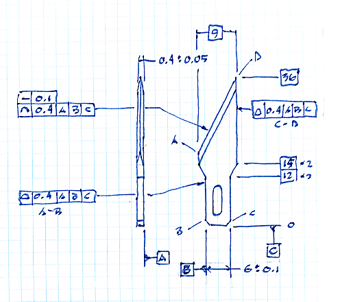
Here is the overall shape. I would have a note specifying a sharpness test on the blade. I would specify the material, and the R[sub]C[/sub][ ]hardness.

Note how I am specifying the profile of an edge for the blade. I care about the aesthetics of it being straight. I proposed earlier that the end of the blade should be the datum[ ]B feature, but I reconsidered when I looked at this. The blade end is a poor orienting feature.

--
JHG
 
drawoh,
Thank you very much for taking the time to make this drawing.
This is very similar to the way I would dimension this product.
The only concern is regarding profile of a line and straightness applied to the cutting edge. The descriptions of these controls in the standard are formed in such a way, that they can only be fully defined when applied to line elements along a surface, that sets the orientation of the tolerance zone. The keywords are: "the tolerance zone is normal to the true profile of the feature at each
line element." (Para 8.2.1.2 for profile of a line). In case of an edge such as the one in this example, the orientation of the "true profile" is ambiguous. This is the reason that Dean suggested a "PROJECTED EDGE" modifier, along with a supplementary definition of the projection direction, is needed. Once again, thank you for the effort. I appreciate it. Unfortunately I had to re-register in order to respond. My previous account is blocked on this site. I hope I will be allowed to participate with the newly registered one.

3DDave, if I said anything offensive, I appologize. I did not mean to act in a rude manner.
 
drawoh,

On your sketch, what controls location of the edge in the direction of blade thickness? What controls angular relationship of faces forming the edge?
 
pmarc, I would have made [A} the thickness and then the blade cutting faces could be symmetrical to that. Anglularity and sharpness test take care of the rest. Other than that - it's sufficient for the outline.
 
pmarc,

I forgot to define the blade shape. I need a section view to define the angles. I need to apply a form tolerance to keep the sharp edge straight with respect to datum[ ]A.

3DDave,

I have no objection to using the thickness as the datum[ ]A feature, since this is accurate, and since the blade edge is symmetric to the thickness. I am far more concerned about straightness than I am with the actual location of the blade, or its parallelism with the thickness.

Sem_D220,

I have never before used profile of a line. There is no surface to justify the use of a surface profile. The actual purpose of the thing is to control surfaces that are not perpendicular to drawing view, such as a tapered wing of an aircraft. I am reading ASME Y14.5-2009 here, and Fig-8.27 is perpendicular. I claim that the sharp edge is not perpendicular to the drawing view, and there is no area to inspect. It is not possible to define a plane perpendicular to the blade edge, it is possible to define a plane parallel to the drawing view.

SculptureBlade2_dnzzlg.png


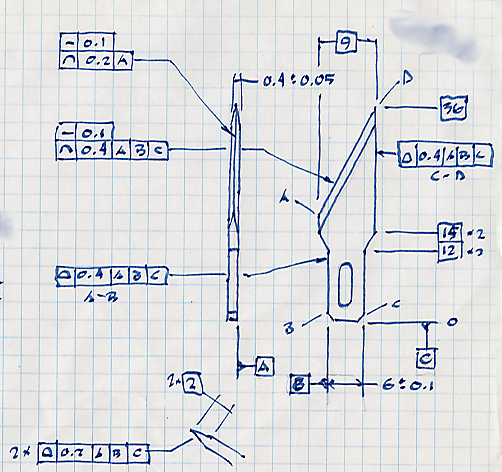
I used a profile tolerance to control the angled sides of the blade edge. I think I should have used the angularity.


--
JHG
 
drawoh,
I think that for the additional control you defined for the edge: straightness within 0.1 and profile of a line within 0.2 to A, you need either a badic basic dimension to A or define A as a feature of size datum feature like suggested by 3DDave.

Straighness is probably valid because according to para. 5.4.1:
"A straightness tolerance is applied in the
view where the elements to be controlled are represented by a straight line"

However, profile of a line is not the same.
It is problematic exactly from the reason you described (the need for a perpendicular plane to set the orientation of the tolerance zone), view dependency for profile doesn't seem to be supported by the standard.
 
3DDave,
By no means I claim to be an expert in defining sharp edges, so perhaps you are right. Perhaps the two tests are indeed able to take care of the rest. I am just not sure it is always smart thing to indirectly control blade geometry (in this particular case, angle between slopes and location of the edge relative to part's center plane) through some test results.


drawoh,
I see what you are trying to accomplish. Unlike semiond (Sem_D220), I believe that Y14.5 supports (rightly or not is a different story) view dependency of profile of a line (see fig. 8-27), but on the other hand I understand why semiond and Dean would like to have a new/standardized tool to deal with cases like this.

BTW. If on your sketch only one side of the thickness is datum feature A, I think you would want to add basic dimension of 0.2 from A to the edge, wouldn't you?
 
If we are going in the direction of making this a complete drawing, I would also add, that there should be either a basic angle of the cutting edge relative to datum B or a vertical basic dimension in addition to the existing horizontal 9 basic dimension.

pmarc, isn't the tolerance zone in fig. 8-27 perpendicular to the true profile of the controlled feature?
I stand corrected and accept the fact the there is some view dependency here, because due to the view on which profile of a line is defined, "longtidual" line elements are sampled. I assume this is what you meant? However the definition per para "8.2.1.2 Profile of a Line" involving "true profile" that can dictate an orientation is valid for the figure, and doesn't seem to be valid in case of a sharp edge.

semiond
 
semiond,

Agreed on missing basic angle of the cutting edge relative to datum B.

You are right. This is what I meant about view dependency.

As for orientation of profile of a line tolerance zone in case of sharp edges, I am not sure what to think. If you imagine that in fig. 8-27 a second profile of a line tolerance has been added to the other view and we agree that this is valid scheme, I don't think the scheme proposed by drawoh is necessarily wrong/invalid/ambiguous.

The reason I said I am not sure what to think is simple - I do not like view dependent tolerances by definition and firmly believe they should go away from the standard as soon as possible. In ISO GPS they realized that some time ago and that is why they developed Intersection, Orientation and Collection Plane indicators.
 
drawoh, if the blade is symmetric, the edge will be straight in that direction, even if it's a fancy scalloped edge. I am not sure how profile or straightness apply to the edge-on view of an edge.

pmarc, the sharpness test is because the tiny geometry at the edge of the part is far too expensive to inspect and making a functional test is sufficient for all but experimental purposes intended to perfect production and performance. I would also emphasize that profile of a surface applies to the front and the back whether there is a noticeable side joining them.
 
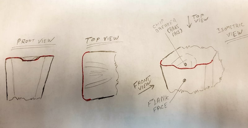
Here is another example.
This is typical geometry of a grooving insert. The cutting edge emphasized in red. Unlike in the case of the blade which was dealt with by drawoh, where opinions were expressed that it can be succesfully defined by the means of profile controls without any additional standardized modifiers/notes, the outline of the cutting edge in this case doesn't appear as a straight line in every view. Therefore in my opinion, can't be described through 2 flat tolerance zones for a line element intersecting at the theoretical "true" edge. For cutting tools the wedge angle (between the flank and the rake faces) is usually less than 90°, and what you see in the top view as a straight line is not the entire flank face, but only the edge. Sometimes the flank is not a flat face at all, and includes a "compensation" convexity so that the edge remains straight enough in spite of it's dendency tendency to become concave because of the effect of the chip breaker's concavity. What should be inspected is the location of the cutting edge relative to datum features, it's resultant straightness (in the top view), and orientation (such as perpendicularity) relative to datum features.

Do you think that this case can be dealt with without the "PROJECTED EDGE" modifier, and a note specifying the projection direction (which can be defined by the means of fixed orientation in relation to datum features)?
20180711_103712_oaojsd.jpg
 
Sem_D220,

You have a top surface and front and side surface all of which can be controlled by surface profiles. The sharp edge is where these faces intersect. Is that a problem?

The sharp edge needs to be controlled by some cutting test.

--
JHG
 
drawoh,
Controlling the cutting edge by applying surface profile on the intersecting surfaces is an indirect method to control edge geometry and it is both more complicated and less reliable.

Here is another example: if you were required to measure the point angle of a drill bit, to verify it's 118° within tolerance, would you even think of attempting to measure it through scanning the flutes and relief surfaces and letting a program calculate the geometry of their interesections? Why not? Theoretically the edges that form the point angle can be determined from the interesecting surfaces' geometry. But obviously it is not worthwhile to even try. Of course that this is only an example to demonstrate a principle. Yes, point angles of drills are usually defined with direct +- angular tolerances and I'm not saying that there is a problem with that. But there are other applications that do benefit from use of geometrical controls (feature control frames), as long as those controls are applied directly to the important feature - and sometimes it's the edge.
 
drawoh,
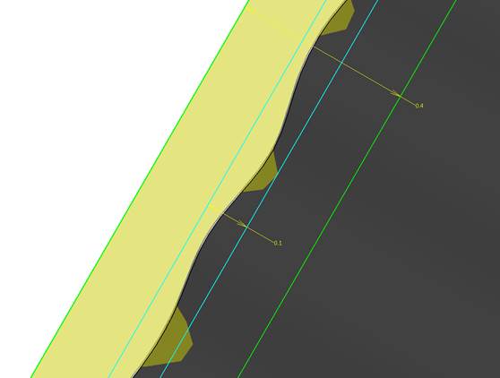
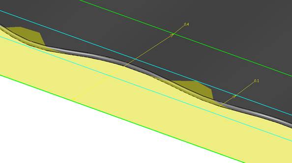
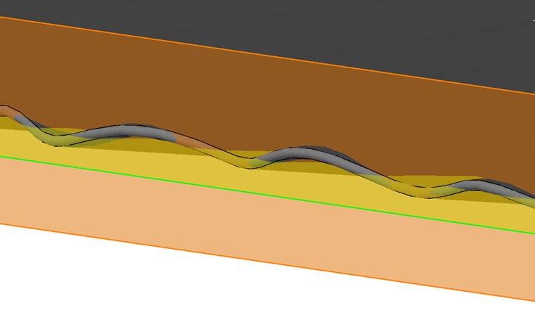
I modeled a possible as-produced edge for the blade drawing you made. It seems like any real edge produced will fail to fall within the 2-dimensional profile of a line tolerance zones. Please check these pictures:

image003_duh6ch.jpg


image005_prsy0b.jpg


image007_fktvtj.jpg


The yellow transparent tolerance zone in the first and second images is the 0.4 profile you specified. The blue limits are the straightness refinement. The transparent orange tolerance zone in the last picture is the 0.2 profile from the other view.

There will always be portions of the edge outside both tolerance zones, regardless of how accurate it will be produced.

For the profile tolerance zones to be understood as you meant them to be, and as they are applied in reality, they should be applied on a projected outline, and not as defined by default in the standard.

3DDave will claim I want a "magic wand solution" but there is actually nothing magical in Dean's suggestion, only making the standard a little bit more in line with the reality and methods that are already well established.
 
Semiond,
I can't imagine that anyone could have complained about your posts. You have been very polite in this discussion, at least.

Your illustrations of why profile of a line doesn't work on the edges that have been discussed are very good. This helps explain why some other tool (a modified version of profile) is needed to directly control an edge.

When 3DDave kept bringing up edge sharpness considerations that I think are not relevant to this discussion, I should have thought of bringing up another example for which profile modified with "PROJECTED EDGE" is useful.

I wish I had time to provide pictures, later this week I may be able to (if my 5 kids on Summer break magically become "self-busy" with good things to do).

The other example is when a molded plastic part has a planar feature that is drafted (at a draft angle anyway) (I'll name it feature "D") that creates an edge where it intersects with another planar surface (with name feature "ND"). For this example, the included angle between features D and ND is 88 degrees. If the mating feature, on the mating part, does not have complementary draft with feature D, but is instead designed to be perpendicular to feature ND, then the surface of feature D is not functional. Feature D's surface in the assembly is not touching anything but air. The edge created between feature D and feature DN is functional, because a mating feature is located by the edge. Because feature D's surface is not critical, control of feature D can be efficiently left to a profile of a surface applied using a general note (which is included to apply to any feature characteristic without an explicitly applied tolerance).

A view with a projection direction that is normal to feature ND can be used to point to the edge and apply profile of a surface (or profile of a line, if that is what is deemed better and eventually added to Y14.8 and/or Y14.5) modified with PROJECTED EDGE. The necessary basic dimension can be shown in the same view and need only to to to the edge between features D and ND. The tolerance zone needed is two parallel planes that are normal to feature ND (they must be parallel planes, rather than parallel lines, to accommodate the fact that feature ND will not be perfectly flat, so the edge will have straightness error in the projection direction that must be accommodated by the tolerance zone).

No sharp edge is involved in this example, so I hope this makes it clear why I said all of the talk about how sharp edges are controlled was irrelevant to this discussion. The edge will never cut anything. It will have a mating feature though, so its location should be directly toleranced.

We don't currently have way to specify this, so some sort of modified profile tolerance is needed. Profile as it is defined will not provide a tolerance zone that is being described for a PROJECTED EDGE modified profile. Two parallel planes that are parallel to a projection direction of a given view, applying to an edge (so not normal to any true profile), is not supported by any GD&T standard that I know of.

Later, when the new standard on direction and force indicators has been released, we won't have to rely on a view projection direction or a note to describe a projection direction using words.

Dean
 
Dean,
Thank you very much for the support on this matter.
The additional example you brought up is very good. I think I am able to predict the objections of other forum members to this example. The main argument will probably be that since the face "D" is what mates on the part and the counterpart, the face should be controlled for location and not the edge. I have an answer prepared ahead: usually these kind of claims have a good basis, but a drafted face is a good example to an exception from that common concept. The reason for it is that in order to locate a nominally flat face, it is convenient to have a parallel face to it that can be used as the datum feature for location. If for example the datum reference is perpendicular to face ND, then you have a 2° angle between the face to be controlled and the datum reference. This means that for verfication of location, a distance should be measured at some basic location on the "D" face. This does complicate things unnecessarily. If you locate feature D by the edge to the datum reference and conroll control the angle sufficiently, then it's simpler, more efficient, and good enough for most cases.

I'd like to add that perhaps once the direction of projection is defined and a PROJECTED EDGE modifier appears on the drawing, it is possible to treat the measured projected image in the vision system, measuring microscope or an optical comparator, as a two-dimensional entity. Therefore, tolerances such as straightness and profile of a line, which are 2-dimensional, can be applied. Perhaps it would be more "intuitive" to most. When drawoh presented a blade drawing utilizing profile of a line and straightness controls applied on the edge, no questions were raised by the other users regarding the relevance of the 2-dimensional tolerance zone to a real 3-dimensional edge. That is because without even acknowledging this, everyone probably interpreted the tolerance zone as a "projected" one. On the other hand, if profile of a surface and a flatness refinement were used instead, I believe that people would start to scratch their heads, as those controls are clearly associated with surfaces.

Thank you for your input, and good luck with keeping the kids busy :)
 
Status
Not open for further replies.
Back
Top