Eng-Tips is the largest engineering community on the Internet

Intelligent Work Forums for Engineering Professionals

  • Congratulations waross on being selected by the Tek-Tips community for having the most helpful posts in the forums last week. Way to Go!

Coplanar datum / common datum features with more than two surfaces 3

Status
Not open for further replies.

random_guy

Mechanical
Jul 16, 2010
72
0
0
US
I have a long (15'), thin, extrusion with cuts perpendicular to the length. Essentially as shown below.
Coplanar_Profile_gubbml.jpg


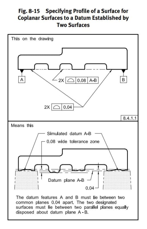
I want my primary datum to be where all the surface profiles in the image above are applied, in order to facilitate gaging of the slots to that primary datum. The top surface is also interrupted with slots.

4.12.1 (2009) specifically states "...coinciding with the datum feature simulator that simultaneously contacts the high points of two surfaces." (emphasis added).

This is also addressed in 2018 (Common Datum Features, 7.12.1) where two surfaces are again specified.

While I can see the reasoning (3 pts to form a plane), the example as given (supported on the ends) would result in sag in the center for long and thin parts, and my profile measurement would be useless. I don't see why this shouldn't be applicable for more than 2 surfaces (think surface plate inspection). The surface was one continuous surface prior to machining of the slots.

Your opinions would be appreciated!

Wise men learn more from fools, than fools do from the wise.
 
Replies continue below

Recommended for you

The quote you give from the 2009 standard omitted the first part of that sentence, which contains the answer to your question:
"Figure 4-23 is an example of a single datum plane simulated, as explained in para. 4.12.1, by coinciding with the datum feature simulator that simultaneously contacts the high points of two surfaces." (my emphasis)
So the mention of two surfaces applies to that example. It's not meant to be a blanket rule. If you wanted to, you could hyphenate 4 surfaces as one "common datum," although in the real world the 3-point contact that forms the true plane may never touch some of the four surfaces. But that's true of any datum.

John-Paul Belanger
Certified Sr. GD&T Professional
Geometric Learning Systems
 
Thanks, I suppose perhaps I was reading too much into the example. I knew this was acceptable but was having trouble proving it in the standard.

The sentence immediately after, "Identification of two features to establish a single datum plane may be required where separation of the features is caused by an obstruction, such as in Figure 6-6, or by a comparable opening (e.g., a slot)." (emphasis added) only serves to further cause confusion.

In this case, it is not speaking of the specific example but of a general scenario, which is confusing as the number two is again used.

It should have been written to say "Identification of two or more features to establish a single datum plane may be required..."

I'll have to add it to my list of Y14.5 grievances. [upsidedown]

Wise men learn more from fools, than fools do from the wise.
 
Hi, random_guy:

Your part sounds like a flexible one. You need to consider how to restrain it in order to establish your primary datum. If you can post part of your print, or show a sketch, we better assist you.

Best regards,

Alex
 
Hi Alex,

I can't, unfortunately.

It's not a flexible part, it's a custom aluminum extrusion with a fair amount of post-machining. It just becomes "flexible" when only supported at the ends over a 15'-20' length.

The primary datum will be the surface in question (a long side), and it will be laid on a gage that will interlock with certain features on the extrusion and have a handful of pin checks.

I just wanted to get concurrence from others on here that I wasn't violating Y14.5 by utilizing the entire interrupted surface as a single datum.

I think I'm all good now, thanks!

Wise men learn more from fools, than fools do from the wise.
 
Hi, random_guy:

Your part is flexible according to your statement below:

"the example as given (supported on the ends) would result in sag in the center for long and thin parts, and my profile measurement would be useless."

You need to think math definition of the primary datum. How do you position your part when it is machined and/or inspected?

Best regards,

Alex
 
How will you label and use the "common datum features" in a feature control frame if the part is long, as you say, and the bottom face is interrupted by multiple slots? Will there be some profile tolerance feature control frame that reference something like A-B-C-D-E-F-G-H in one compartment?
 
Jassco - when I think of flexible parts within the scope of Y14.5, I think of things like gaskets, O-rings, seals, etc. Not metal. I get what you're saying but I don't think it qualifies as flexible. When I say it will sag in the center, I don't know how much but likely no more than .05". So, at what point do we define what is flexible? We have equipment in our lab capable of measuring the sag of short lengths of I-beams, which is in the tens of millionths. But we wouldn't consider an I-beam flexible.

When the extrusion is machined and inspected, it will be on the primary datum that is that interrupted surface (both sides). This is the most practical way of doing it. It's just trying to make it fit within the scope of Y14.5, and the multiple references to two surfaces (and not two or more surfaces) was throwing me off.

Burunduk - Instead of labeling between each surface in that manner, I intend to use a phantom line extending across the gaps, with a note below the FCF that the datum is attached to indicating "6X SURFACES" or something to that effect.

Wise men learn more from fools, than fools do from the wise.
 
All parts are flexible. The way Y14.5 treats the problem sucks. What is more important is free-state vs specifically constrained vs the expectation that the weight of the part is sufficient to make useful contact with the datum feature simulator. Typical constraint, either by self-weight or by additional external forces, should duplicate the installed condition.

Odd things can happen - only one of the multiple surfaces may make contact with the datum feature simulator; this poses a problem if a CMM is used to "fit" the multiple surfaces in that it won't properly simulate the installed deformations.
 
random_guy said:
So, at what point do we define what is flexible?
It's flexible if the geometry is considerably different in the free state condition than in the installed condition in the functional application. "Considerably" means it is likely to affect the tolerance evaluations. Check figure 7-52 of ASME Y14.5-2018 for how a flexible part is treated. However, note that the figure is very incomplete: a coplanarity control for the faces of datum feature A is needed (likely in the free state) and the restraint note should provide all the necessary details of how to apply the restraint. Ignore the fact that the example and text describe only two coplanar surfaces - you can extend it to your case of multiple contact areas.
 
Thank you both, great info. I spoke with the customer yesterday and we agreed on a plan to restrain the part in a gage in a similar fashion to its use.

I appreciate all the help!

Wise men learn more from fools, than fools do from the wise.
 
Status
Not open for further replies.
Back
Top