Eng-Tips is the largest engineering community on the Internet

Intelligent Work Forums for Engineering Professionals

  • Congratulations waross on being selected by the Tek-Tips community for having the most helpful posts in the forums last week. Way to Go!

Correct measuring practice for sheet metal parts 1

Status
Not open for further replies.

Deyaab

Mechanical
Jun 13, 2016
6
0
0
EG
Hello

Please could you advise me with regard to the correct measuring practice for the following air bending patterns to get the correct bend dimensions and angles :

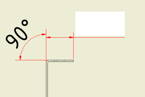
1. 90 degree bend (Edge to bend)
Folded_ro8udb.jpg


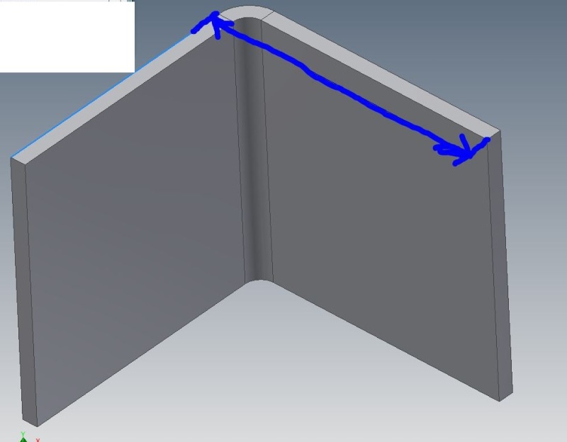
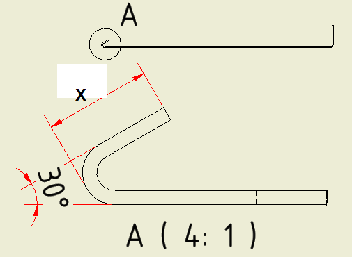
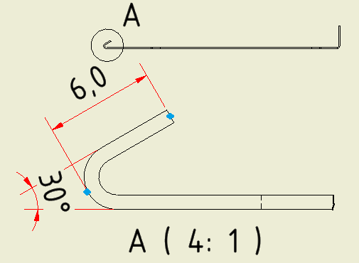
2. Acute angle bend (30 degree) (Edge to bend)
Baby_incubator_f06iz2.png


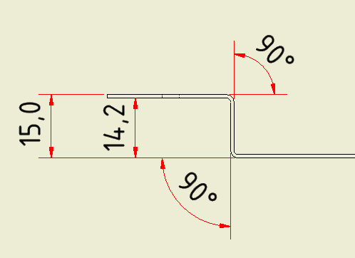
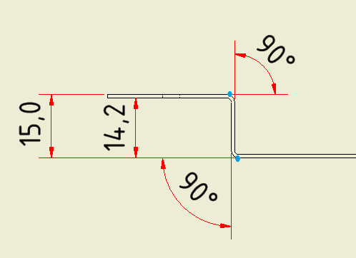
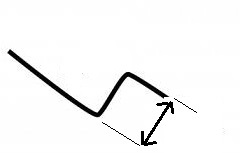
3. Offset 90 degree bend (bend to bend). 2 bending steps
bending-basics-article-strategies-for-forming-offsets-0_mio4vk.jpg


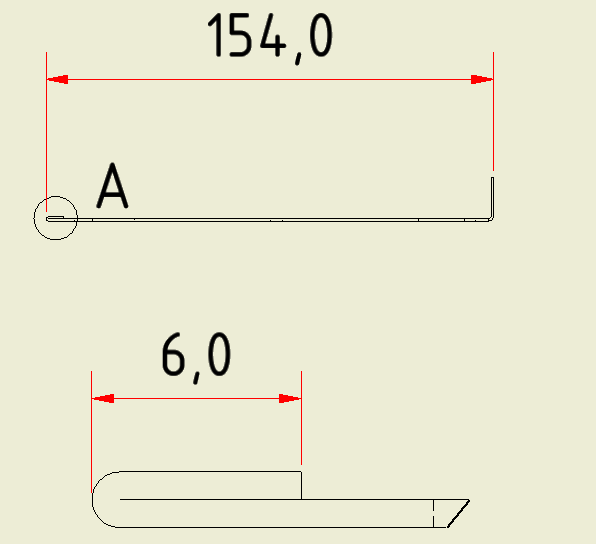
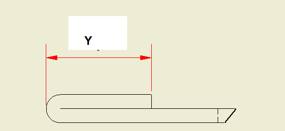
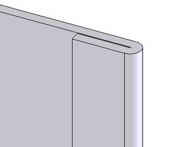
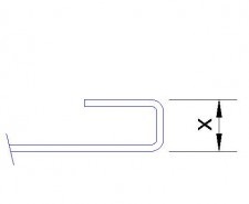
4. Closed and open hem (edge to bend)
Hem_sheetmetal_nx300f.png


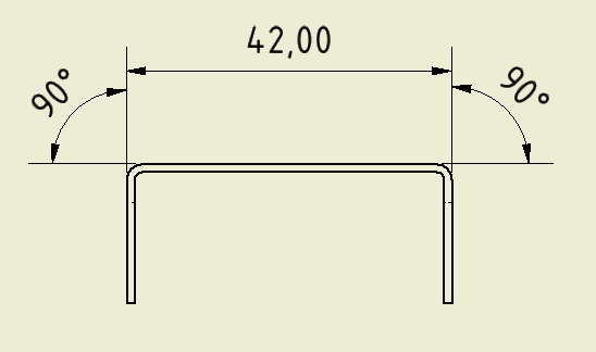
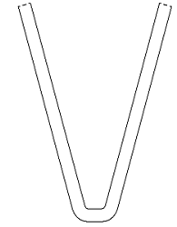
5. U bend ( bend to bend). 2 bending steps
U-BEND-sidebar1_1_cd3na8.jpg
 
Replies continue below

Recommended for you

Since the parts you have shown can be dimensioned in several different manners , you should go by what the draftsman has shown on the drawing.
That said, bend one can be dimensioned inside or out.
Bend two; If that is a continuous radius then an overall dimension and angle to the theoretical intersection of the two sides with the inside radius given. if in fact that is two sharper radii with a straight in between then that should be detailed to the center points of the radii and the angles and distance between the two rads given.
Bend three; Should be given as an inside to outside dimension, to avoid metal thickness variations.
Bend four; A hemmed edge should be dimensioned on the overall dimension of the wall on which the hem is formed, the hem itself should be a non critical dimension.
Bend five; On this type of bend the bend nearest the short flange is bent first and the second against the long wall is bent on a gooseneck die. The dimension X may be controlled by the size of the die. On thinner metals this operation may be done by a beam folder with a cut away nose, with short bends there may be slippage as the part is bent. the bends can be dimensioned as either inside bends or outside bends as shown.
B.E.

You are judged not by what you know, but by what you can do.
 
Hi All

Thank you Berkshire and Kenat for your reply

The features dimensioned as follows:

Please I need to know the correct measuring practice using a vernier caliper and square angle

1. 90 degree bend

1_q741v9.png


2. Acute angle bend (step before closing the hem)
2_ii46ag.png


3.Offset 90 degree bend (2 bending steps)

3_ylm2db.png


4. Closed hem

4_dsxzal.png


Mr.Berkshire: Do you mean dimension 154 mm to be measured only not 6 mm?

5.U bend (2 bending steps)

5_jt1waw.png


Thank you!
 
Item 4 the 154.0 mm dimension is the critical dimension, the 6mm dimension is merely the result of the flattening operation. Your ninety degree bend, and your long dimension are your critical dimensions. The 6mm dimension should be allowed to float. If for any reason the 6mm dimension has to be a hard dimension , then it should be done first and gauging for the other bend should be done from there , in which case the vertical dimension should be allowed to float. You do not get something for nothing, locking down dimensions on sheet metal products merely drives the cost up ,even on precision sheet metal parts.
B.E.

You are judged not by what you know, but by what you can do.
 
Thanks Mr. Berkshire

I got your point about Closed hem.

Please Could you check the following questions also:

1. For closed hem, please confirm that there is no change in 6 mm dimension from 30 degree bending position to closed hem position.( i.e: Dimension X= Dimension Y)
2_xdetyk.png

4_cagcmm.png


2. For hem, Should I use a different K factor value to which used with 90 degree bends?

3. To measure the dimensions shown in the following pictures, Should I make the jaws of vernier caliper at the blue points:
2_j8wrmw.png

3_afmekg.png


Sorry for my bad English
 
Deyaab,
There will be a change in the dimension X at 30* to dimension Y at 180* Your K factor will not change , what will change is the inside bend radius.
You are going to have to find this dimension by trial and error for a precise dimension.
What will happen is that your 6mm dimension at 30* when you check it will be correct. When you measure it again as Dimension Y it will have grown a little due to the loss of radius in the flattening operation .
In the second operation, the double offset, whilst you can measure the 15mm dimension, measuring the 14.4mm dimension from, inside edge to outside edge gives more consistent results because this takes out the variations in the thickness of metal. Think what would happen if your metal was .45mm instead of .40.
B.E.

You are judged not by what you know, but by what you can do.
 
Status
Not open for further replies.
Back
Top