Eng-Tips is the largest engineering community on the Internet

Intelligent Work Forums for Engineering Professionals

Correction power factor 3

Status
Not open for further replies.

Emadshaaban1987

Electrical
Apr 30, 2020
58
0
0
LY
Hi folks
I understood the importance of CAP bank for the big individual customers to reduce the paying bells,
hence , helping to improve the network efficiency by reducing reactive energy that cause more losses and heats .
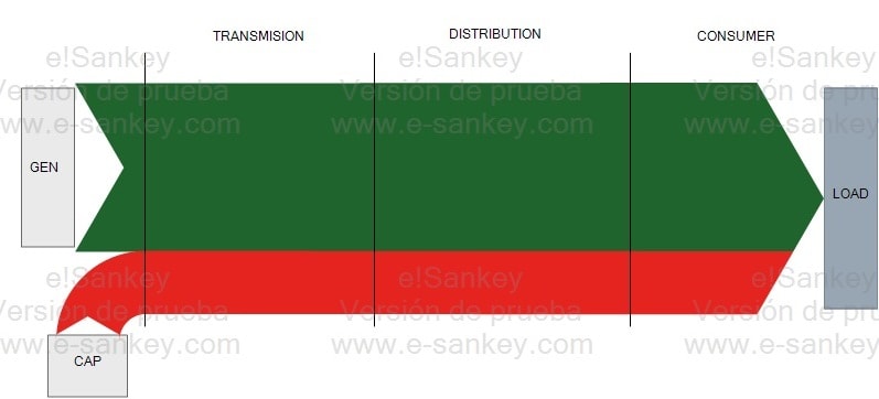
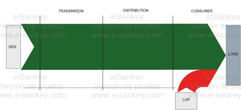
Based on that, why don’t the generation companies connect automatic CAP banks near their location?
Does the location where the Capacitors important? or it can be connected where ever in the network ?
 
Replies continue below

Recommended for you

A poor power factor has the effect of reducing the kW capacity of transformers and conductors.
As an example, a 1000 KVA transformer will pass 1000 kW at 100% PF but only 800 kW at a PF of 80%.
The location is very important.
In the example above, raising the PF from 80% to 100% on the secondary of the 1000 KVA transformer will increase the capacity from 800 kW to 1000 kW. It will also reduce some of the transformer losses.
Raising the PF from 80% to 100% on the primary of the transformer will have no effect on the transformer.
Power companies do use automatic capacitor banks to compensate for reactive currents.
Some reactive currents are caused by utility owned transformers and by line reactance and are the responsibility of the power company.

Bill
--------------------
"Why not the best?"
Jimmy Carter
 
See below for a very nice way of "viewing" what waross said.

In a simple general case the load needs a certain amount of reactive energy, and you have to supply it one way or the other.

Location 1: Caps near generation side.
FAR_opp6nr.jpg

See that the reactive energy (red in the graph, green being active energy) will circulate all the way through the grid from generation to consumer, lowering the lines and transformers capacities and increasing the losses in every step of the way.

Location 2: Caps near the load.
CLOSE_aodzvu.jpg

Now the reactive energy is supplied locally and the rest of the grid can work more lightly (less losses) or supply more active power (with the same losses).

You usually compensate reactive energy as close to the reactive source as practical or cost-effective can be made.

With these images in mind you won't forget the basics ever again!
 
Dear Mr. Emadshaaban1987

Q1. "...I understood the importance of CAP bank for the big individual customers to reduce the paying bells, hence , helping to improve the network efficiency by reducing reactive energy that cause more losses and heats .."
A1. The learned contributors advice are correct. I would like to submit my opinion on some facts that is not mentioned by the learned contributors:
a) "... big individual customers to reduce the paying bells..." is due to different utility charging system. For "small/domestic" consumers the charge is based on [kWh] consumed. There is No penalty or any extra charges on low pf. For "big/industries taking MV supply, the charges is based on [kWh and kvar] or some other forms where "heavy" penalty is imposed on consumers with low pf.
b) The motor (kW) or the transformer (kVA) ratings remain the same, irrespective of the system pf. In this sense, there is NO improvement in their [efficiency].
c) It is correct to say that a 1MVA transformer would deliver 0.8MW at 0.8pf.
d) It is NOT correct to say that a 100kW motor would have the output reduced to 80kW when running at 0.8pf.
e) It is correct to say that the {running current} would be [lower] when operating at a [higher] pf.
f) Due to higher running current at lower pf, the heat losses (IxIxR) would be higher.
Che Kuan Yau (Singapore)
 
e) It is correct to say that the {running current} would be [lower] when operating at a [higher] pf.
This is misleading.
Adding capacitors to a motor to improve the PF does nothing to change the running current of the motor.
It reduces the current in the circuit feeding the motor, but does not change the motor current.

Bill
--------------------
"Why not the best?"
Jimmy Carter
 
In a nutshell, the DNO can supply you with reactive power, but this costs them extra so they pass the charge on to you - higher current and losses to deliver less real work. It would be interesting to hear an explanation of why it's so inconvenient for DNOs since I personally don't know why either.

It's usually more cost-effective to DIY. If the transmission network had PFC then they would need correction in too many places at once.

Capacitor banks are pretty cheap, although if you really wanted to there are much more complex bits of kit that will give you a very precise power factor.
 
The PF charges are a penalty intended to motivate customers to correct their PF.
As a penalty, the PF charges are often much more than the cost to the utility of the poor PF.
Payback time for PF correction is often under one year.
There are exceptions in regards to payback time for special cases.

Bill
--------------------
"Why not the best?"
Jimmy Carter
 
While kinda already been said, PF correction can increase the margins for in-plant switchgear, subs, and MCCs approaching their bus amperage limits, due to various equipment added-on through the years.
 
The best place to correct PF is at the loads that create a lagging PF, namely induction motors (for the most part). If you correct it higher up, and inductive loads come on and off, you can end up over correcting and having a leading PF, which can be just as bad (for different reasons) that a lagging PF. Also, when you have grid capacitors, they end up contributing to voltage spike whenever the grid is switched up stream, which in the NIMBY* world we live in, is happening much much more than it used to. By using "At Load" PFC, you switch small capacitors on WITH the induction motors when you run them, so they are off-line when you don't.

NIMBY = Not In My Back Yard, referring to the fact that everyone wants more power now, but nobody wants the infrastructure it requires to be in their area, affecting their property value. So utilities are forced to keep making their existing infrastructure work to get power to more and more people, resulting in more grid switching to move it around from where there is in excess to where there is demand.


" We are all here on earth to help others; what on earth the others are here for I don't know." -- W. H. Auden
 
Another advantage of switching the capacitors with the motor is a slight reduction in starting current.

Bill
--------------------
"Why not the best?"
Jimmy Carter
 
Agreed, auto-switching capacitor banks are more desirable. But one has to properly size every switching step to match with your auto-running equipment in the facility! I've been stung by that once and the PFC bank just keeps on switching over and under-correcting!
 
That's a poor controller if it doesn't stabilize. Good ones will know the step size and only add steps that get close to unity but still lagging. If they go past unity to leading they back off steps until the power factor goes lagging again but know not to add steps again.

I've seen lots of utility billing structures where just correcting the power factor near the maximum facility load would stop any extra demand charges.
 
My method was to look at the KVARHrs on the power bills going back at least a year and preferably two years.
Adjust the numbers to indicate 30 day KVARHr consumption and then add enough capacity to correct all but the worst month to about 92% average PF.
The extra cost to correct the worst month in two years was seldom worth the effort.
Also, ignoring the worst month resulted in less possibility of overvoltages at times of light loading.
Did you mean PF penalties rather than demand charges?

Bill
--------------------
"Why not the best?"
Jimmy Carter
 
Yes, demand charges. Every utility around here charges for the energy used plus a demand charge based on the higher of the kW or 90% of kVA measured over a 15 minute window. Correcting the power factor to get 90% of kVA demand equal or lower than the kW demand gives the only savings power factor correction can provide.

You need to know how the utility is charging you before you go putting capacitors onto a system. You will never pay back the capacitors if there is no penalty for low power factor.
[pre][/pre]
 
OK. I see how that works.
That may be a little more punitive than the tariffs that I have worked under.
100 KWHr at 80% PF will be 125 KVARHr.
90% of 125 KVAR = 112.5 KVAHr billed. A penalty of 12.5%
Under the tariffs I am familiar with, 100 KWHr at 80% would be a penalty of 90% - 80% = 10%.
100 KWHrs plus 10% would be 110 KWHrs billed.
Thank you for your information.
Different strokes, but the customer pays regardless.
Your system has the advantage that the payback is quicker.

Bill
--------------------
"Why not the best?"
Jimmy Carter
 
Every half cycle, reactive energy flows from the magnetic fields in the inductive loads, through the power grid out a capacitor, then back through the grid to the inductive load. Real power only flows once from the generator to the load. This means supplying all the reactive power from the generator would force the reactive power to flow 120 times further than the real power flows. Thus, capacitors tend to be installed close to inductive loads. In addition to the distribution capacitors on the grid to offset custom loads, the transmission utilities have capacitors on the transmission grid to offset the inductance of transmission lines.

Although putting capacitors near loads reduces the losses caused by reactive power flows, capacitors provide only large discrete steps of the amount of power they produce. Often capacitors are either fixed on a seasonal basis, or have just a few discrete steps than can be mechanically switched no more often than once per five minutes. In order to fine tune the total amount of reactive power produced at any instant, traditional synchronous generators such as hydro/steam/coal/natural gas can either supply or received reactive power. A traditional generator can change reactive power output in fractions of a second, and can generate any amount within the nameplate rating, rather than just discrete steps like a capacitor bank. This reactive capability of traditional generators cost almost nothing, so there is no need for capacitors at a traditional generator.

Newer kinds of generators such as wind and solar lack inherent low cost reactive capability, and instead use a combination of mechanically switched capacitors and power electronic controls to simulate the reactive output of a traditional generator. Wind farms usually need a fair amount of capacitors to offset inductance in the many miles of cable interconnecting all the generators, as well as the inductance of the wind farm transformers.
 
Status
Not open for further replies.
Back
Top