Continue to Site

Eng-Tips is the largest engineering community on the Internet

Intelligent Work Forums for Engineering Professionals

  • Congratulations IDS on being selected by the Eng-Tips community for having the most helpful posts in the forums last week. Way to Go!

Countersink positional tolerance interpretation

Status
Not open for further replies.

Burunduk

Mechanical
May 2, 2019
2,369
Considering the tolerance of position for a countersink as shown in this video

Would you interpret the position requirement (when considered for the countersink feature), as applying to the cone axis, or to the center point of the circular element which is controlled for size ø.675-.685?
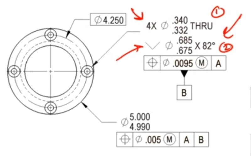
Screenshot_20230216_122552_YouTube_caui43.jpg
 
Replies continue below

Recommended for you

Jassco said:
There is nothing in ASME Y14.5 that indicates cones are features of size.
That is YOUR opinion. Looks like other(s) (other being even a committee member) have a different opinion.
And in this point in time, unless you PROOVE otherwise, I will believe (or prefer to believe) the committee members (with credentials described in the previous indicated thread).

And copying and pasting paragraphs and versets from the standards are not helping your cause unless you provide a clear opinion based on the above standard requirements.


There is no clear example in the standard of a cone used as a feature of size. The creators of the latest math standard also have no such example, but they do indicate that spheres of constant, appropriate radius for the smallest and largest limits and their associated spines define features of size.

It's small surprise that the 14.5 and 14.5.1 committees don't talk to each other as the '2019 version of 14.5.1 describes the '2009 version of 14.5 and not the '2018 version of Y14.5, but in spite of that neither shows a cone as a feature of size.

I think the two "is a cone a feature of size" groups have decided to leave it ambiguous rather than continue fighting about it because it rarely ever matters.

Those in the "yes" groups portray it that way in their training material and those in the "no" group don't. The "yes" group skips the math standard definition that excludes the option.

If it mattered (which it did one time for a design I was working on) I would define it with position tolerance on a gauge sphere to specify both vertical (depth) and horizontal (transverse) locations, though likely with bidirectional position tolerances to separate the vertical and horizontal components for the thread OP example.

 
There are some examples in Y14.8 where the size at a certain basic length is shown for a cone, so I am thinking that adding a position callout to that size ( circular element, center point) is not much of a leap.
 
greenimi, any specific example where the size at a certain basic length is shown for a cone? I have access to Y14.8-2009. Thanks.
 
Burunduk said:
greenimi, any specific example where the size at a certain basic length is shown for a cone? I have access to Y14.8-2009. Thanks.

I am thinking fig 3-9/2009 where Ø18.9±0.1 and Ø17.5±0.1 are shown to be applied at 23 and 6 basic dimensions respectivelly.

Now, if you add a position callout to those dimensions (or to at least one of them) I would think that the location of the circular element (of that drafted feature shown in the picture) is controlled.
 
greenimi, thanks for the example, but this method requires specification of some intermediate diameter(s), while the usual Y14.5 way to specify the c'sink size is the largest diameter, which is at the top.
But, what in your opinion would be the interpretation if the position tolerance FCF was attached under "ø20+/-0.1 -DFT" of figure 3-7 in the same standard?
I think the way this size defined has something in common with the typical c'sink.
 
Burunduk,
I think you are asking about continuous improvement.
Probably 2009 is not very clear, but I think the next revision of the casting standard (the version which introduced the FF full feature symbol) interpret your question from your last reply as being the positional callout applied to the circular element by default. Only if FF is shown then the axis of the cone (instead of a point) is considered.
 
Hi, Burunduk:

The conical surface is not an FOS.

However, you can apply a position tolerance to a circular element per the standard. This is what ASME Y14.5 says about Regular Feature of Size:

"3.35.2 Regular Feature of Size
regular feature of size: one cylindrical surface, a spherical
surface, a circular element, or a set of two opposed parallel
line elements or opposed parallel surfaces associated with
a single directly toleranced dimension. See subsection 5.2
and para. 5.8.1(e)."

You can define circular elements on the cone using BASIC dimensions. But you don't want to apply it to top edge as it is a derived feature of the cone and the top plane.

For precision cones, engineers generally use gage balls to define locations.

Best regards,

Alex
 
greenimi, thank you for the reminder about FF. That does make the default for a tapered hole per Y14.8 clearer.

jassco,
What in your opinion are the possible consequences of directly controlling the "derived feature of the cone and the top plane" for position? Clearly it is already controlled for size since this is how Y14.5 instructs to dimension the countersink - the diameter applies to the top edge. Thanks again.
 
3DDave,

Imagine that I design a shoulder screw with a tapered barrel. I specify a tapered clearance hole such that the screw is tightened down to its shoulder. There is a clearance between the tapered barrel and the tapered clearance hole. The tapered hole is a feature of size, although it probably would be best to specify it with a profile tolerance. MMC called up on the positional tolerance would be useful, since extra clearance would provide the bonus tolerance.

On a standard flat head screw, the conical surfaces are in contact with each other. They inherently centre the part. In a narrow technical sense, I can interpret MMC on a countersink. I can see no practical use for it.

--
JHG
 
drawoh - tapers aren't covered by the Y14.5.1 definition of features of size.

Still is the problem I had mentioned in the previous long discussion on this - there isn't a single "size" dimension on a taper. Which of the infinite many is reported as the controlling size?
 
Hi,Burunduk:

How would you measure position of the circle on top of the cone? Are you going to use a tape measure or a CMM? If you use a CMM, you would have to measure both the cone and top plane to establish this circular element in order to determine positions. For mission critical applications, using profiles or positions of a gage ball is better. But for OP's application, the position is for the through holes (dia. .340/.332).

Best regards,

Alex
 
jassco,
In the OP application, the position applies to both the countersinks and the THRU holes. It is the same principle which is described in detail in the standard for counterbores. If you don't apply separate position tolerances, the one feature control frame applies to both groups of features.

I think I could locate a center point of the circular edge by a measuring mictoscope. I agree that this should be more difficult with a CMM.
 
"there isn't a single "size" dimension on a taper. Which of the infinite many is reported as the controlling size?"

In the machine tool world the angle or slope of the taper is controlled.
And then there is one diameter that is considered the "gage line" .
The tool holder has a gage line, and the female taper in the spindle has a gage line.
The gage lines of the tool holder and the spindle must both be considered and controlled so tooling can be changed with usefully good repeatability. I suppose in gross cases to also keep the tool holder flange from hitting the spindle nose before the taper seats.

Kaiser Big Plus tooling attempts to achieve that dual contact of the taper and flange and spindle nose for greater rigidity. To make thst work at all the gage lines ( diameters) and flange and nose features need to be controlled mighty close. My recollection from 20 years ago was maybe be better than .001".

 
Hi, Burunduk:

A counterbore (feature of size) can have a position tolerance, but a countersink can't. To say a countersink has position tolerance is like to say a leaf on your desk has a position tolerance. (LOL)

Best regards,

Alex
 
Tmoose - true. Still not a feature of size. Those fits depend on elastic deformation to allow them to fit; more of a regardless of size condition.

The entire tapered surface for machine tool holders is (usually) closely controlled to ensure that the small amount of available deformation will be enough.

Sounds more like a need to control profile variation than an individual size; plus a lot of Dykem and a hardened gauge for test fitting; though interferometry is likely to also be in the mix.

 
jassco,
Then I suppose you disagree with the analysis in the video? They are telling how the chosen position tolerance ensures the proper function of the countersink in a fixed fastener case. If the tolerance as specified applies only to the through holes, a large portion of that content becomes meaningless. I'm just asking... (it's fine if you disagree with them, it's not like they are an undisputable authority or something).
 
Hi, Burunduk:

I don't see the video you mentioned. Where is that?

Best regards,

Alex

 
As Burunduk stated, we don't have to take the producers of that video as the undisputable authority. I notice that their GD&T Wall Chart has a huge goof. They give the acronym S.L.O.F. as Shape, Location, Orientation, Form. Any GD&T beginner should know that it's Size, Location, Orientation, and Form (Shape and Form mean the same thing).
 
Status
Not open for further replies.

Part and Inventory Search

Sponsor