Bogdan_gym
Mechanical
Hi
I hope that you can help me with the following problem.
A steel plate shaped like a disc with a hole in the middle has a thickness of 3 mm and an initial temperature of 20 degrees Celsius. The disc has a radius of 100 mm and the hole a radius of 50 mm. On the exterior surface of the disc the temperature increases linearly from 20 to 200 degrees Celsius and on the inner surface it increases linearly from 20 to 300 degrees Celsius.
I have to determine the stresses and displacements that occur and to plot the temperature variation along the axis of symmetry.
This is what I have done
1. I made the part
2. I made the material, created a section and assigned it to the part and brought the part into the assembly
3. In the initial step I created a predefined field with a temperature of 20 degrees for the whole part
4. I made a new step and I selected coupled temp-displacement and steady state
5. I created 2 boundary conditions, one for the interior surface and one for the exterior surface and entered 300 and 200 degrees.
6. I meshed the part and selected coupled temp-displacement from mesh controls
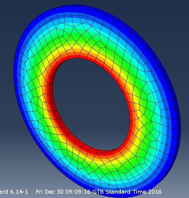
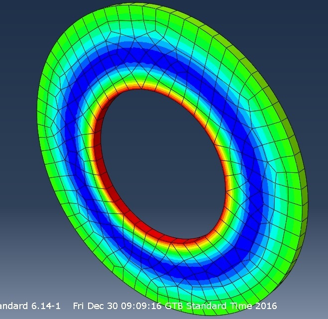
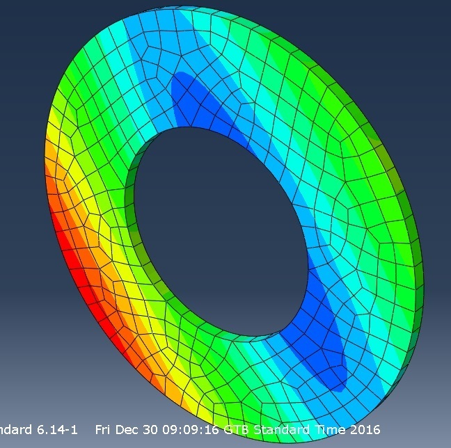
You can see the results in the pictures (temperature, stress and displacement)


My problem is with the displacements.
Why are there regions where the value of the displacement is 0?
Shouldn’t there be a correlation between stress and displacement
Shouldn’t any two points situated at an equal distance and on one side and the other from an axis of symmetry be displaced by the same amount?
I have also made a video where I explain what I have done and what I need help with.
Thanks
I hope that you can help me with the following problem.
A steel plate shaped like a disc with a hole in the middle has a thickness of 3 mm and an initial temperature of 20 degrees Celsius. The disc has a radius of 100 mm and the hole a radius of 50 mm. On the exterior surface of the disc the temperature increases linearly from 20 to 200 degrees Celsius and on the inner surface it increases linearly from 20 to 300 degrees Celsius.
I have to determine the stresses and displacements that occur and to plot the temperature variation along the axis of symmetry.
This is what I have done
1. I made the part
2. I made the material, created a section and assigned it to the part and brought the part into the assembly
3. In the initial step I created a predefined field with a temperature of 20 degrees for the whole part
4. I made a new step and I selected coupled temp-displacement and steady state
5. I created 2 boundary conditions, one for the interior surface and one for the exterior surface and entered 300 and 200 degrees.
6. I meshed the part and selected coupled temp-displacement from mesh controls
You can see the results in the pictures (temperature, stress and displacement)


My problem is with the displacements.
Why are there regions where the value of the displacement is 0?
Shouldn’t there be a correlation between stress and displacement
Shouldn’t any two points situated at an equal distance and on one side and the other from an axis of symmetry be displaced by the same amount?
I have also made a video where I explain what I have done and what I need help with.
Thanks
