Eng-Tips is the largest engineering community on the Internet

Intelligent Work Forums for Engineering Professionals

  • Congratulations waross on being selected by the Tek-Tips community for having the most helpful posts in the forums last week. Way to Go!

Couplings and radial chock load 2

Status
Not open for further replies.

Verkstad

Mechanical
May 17, 2011
44
0
0
SE
Hi!

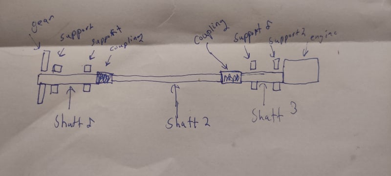
I have a case as shown in the picture below. The shaft between the couplings have no support.

IMG_20230325_212656_cijysm.jpg


The problem is that i get shock loads but not when the engine is running. I have solved the case where i get a axiell shock load by pressing the axis toward each outer hence i get no axial movement of
the coupling (but it would be good to have a coupling who could handle some axial movement)

The case i am wondering about is when i get a radial shock load. I need a couplings with a rated torque of about 800Nm and i get a chock load in shaft 2 of 5kN hence 2,5kN on each coupling. Do you guys have any suggestion on what coupling i could use?
 
Replies continue below

Recommended for you

Thank you TugBoatEng. I have now looked around at gear couplings. The manufacturers do not specify a acceptable radial load. But if you have the coupling geometry you could calculate that yourself i guess. The force would go from the gear to the flange i guess.
 
Hi Verkstad

Can we just be clear here in that a radial load doesn’t produce a torque which you mention in your post. So is it a radial load or do you mean a torsional load?


“Do not worry about your problems with mathematics, I assure you mine are far greater.” Albert Einstein
 
So where does the 800Nm torque come into play?

“Do not worry about your problems with mathematics, I assure you mine are far greater.” Albert Einstein
 
It is the nominal torque i need for the coupling.
I am thinking about a coupling like this one.


I wonder what effect does the grease has on axiell shock loads since fluids cant compress. If one hub move 1 mm in the axiell direction. Would you get high pressure or would it just be high flow speed.
 
Hi Verkstad

The hubs shouldn’t move axially, the hubs are normally an interference fit onto the shafts.

“Do not worry about your problems with mathematics, I assure you mine are far greater.” Albert Einstein
 
Yes but if the shaft move the hub will move even with interference fit. I can not see that this cause a collision in the coupling and it will only happen when the engine isn't running.
 
Hi Verkstad

Can you please tell us which gear coupling you intend to use and also why the shock forces only occur when the engine isn’t running and finally where are these radial loads generated and what magnitude they are.

When using gear couplings the manufacturer usually specifies a gap between mating shat ends and the gap is usually greater than the axial float in the couplings to ensure the shaft ends don’t collide during operation or thermal expansion.

“Do not worry about your problems with mathematics, I assure you mine are far greater.” Albert Einstein
 
Because the item the gearbox and shaft is mounted on get shock loads in a vertical and horizontal direction. But the engine is not being used when that happens.

Have you any suggestion how i could set up this design with out a gear coupling? I sm open for suggestion:)
 
Hi Verkstad

I know no other one other than using some form of coupling for your arrangement.

Regarding the couplings and the radial loads you would need to calculate the deflection of the couplings and then convert this to angular misalignment of the couplings and compare this angular misalignment with that given in the manufacturer’s catalog.

“Do not worry about your problems with mathematics, I assure you mine are far greater.” Albert Einstein
 
The Cardan shaft has a splines slip joint which is essentially a gear coupling. If your misalignments are manageable I would steer away from the high cost of a Cardan shaft.
 
No. Generally gear couplings are allowed to find their own home. My current gear coupling experience is z-drives and the vertical shaft is gear coupled. Gravity sets the shaft to the bottom of the assembly. Previously I have experienced their use in steam turbines quill shafts. Thermal expansion and axial displacement are significant in that case. No springs in any iteration.
 
I have been following this and other forums for many years, and one thing continues to amaze me. Almost NOBODY ever recommends contacting what in my mind is always the best source of knowledge and assistance in cases like this, where the question has to do with the performance of a particular type of commercial item. All the best manufacturers have a complete staff of application engineers, whose ONLY JOB is to help you use their products successfully. Back in the day, engineering offices all had huge libraries of printed catalogs, wonderful source of information and examples. And they all had an 800 number to call for assistance in application. Engineers of that period got used to calling these guys, and we got a lot of help from them. But in these days of "everything is on the internet", the first impulse of young engineers is to jump on Google or some forum and ask their "peers". There's nothing wrong with that at all, in fact I strongly encourage it. But that is only one source of help. The manufacturers themselves are almost always the BEST source.

Call some manufacturers. Ask for Application Engineering. Talk to a LIVE person! Send them your diagram and ask for their assistance. I know its a novel idea but it really works!

Those of you that know me might be getting tired of hearing this over and over again. I get equally tired of reading numerous questions and responses, and not a single mention of calling a manufacturer for their recommendation. Do it. It works.

End of rant. Carry on...
 
Status
Not open for further replies.
Back
Top