BridgeEngineer21
Structural
- Oct 26, 2021
- 58
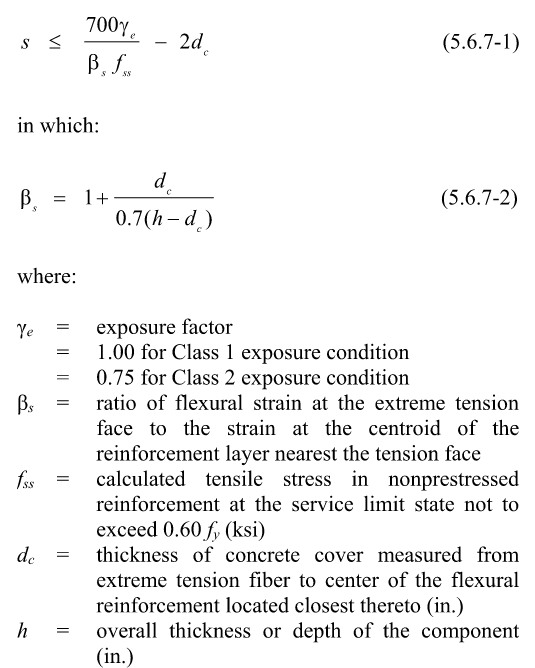
I am reviewing/updating an existing spreadsheet designing post-tensioned I-girders to AASHTO. There is a check included for control of cracking distribution reinforcement in accordance with 5.6.7. I'll copy the relevant equation below so we're all on the same page.

The spreadsheet is now determining fss as M / A * z, with M = maximum moment on the beam at center span, A = area of bottom non-prestressed reinforcement only, z = lever arm. This of course results in a ridiculously high stress because its ignoring the PT, which is then overridden by the 0.6fy limit on fss and a maximum spacing for the non-prestressed reinforcement is just determined based on fss = 0.6fy.
Something seems way off about this. Intuitively I think the actual stress in the bottom reinforcement should be pretty small since the PT is doing most of the work. That could reduce fss well below the 0.6fy limit and decrease the requirement for non-prestressed reinforcement. But if you just go by strain compatibility, with the bottom reinforcement lower than the the PT ducts, the bars would be yielded - and that's how they end up with the extreme stresses the spreadsheet is calculating (8350 MPa/1210 ksi). I very rarely work with prestress and am finding myself at a loss how else to figure the actual stress in the non-PT bars. Could anyone give some advice on this specific situation, or at the least point me to a good reference where I could do some reading on it?
Another wrinkle is this following paragraph from AASHTO, which I don't quite understand and which seems to me to contradict the above definition of fss as for non-prestressed reinforcement.


