Eng-Tips is the largest engineering community on the Internet

Intelligent Work Forums for Engineering Professionals

Crack Control Verification for Prestressed I-Beam

Status
Not open for further replies.

BridgeEngineer21

Structural
Oct 26, 2021
45
0
0
DK
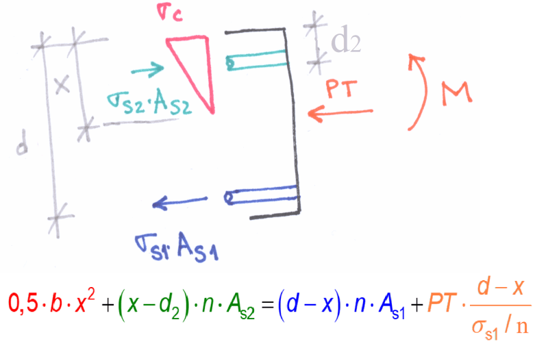
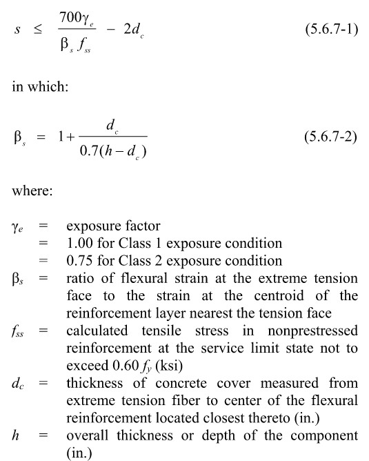
I am reviewing/updating an existing spreadsheet designing post-tensioned I-girders to AASHTO. There is a check included for control of cracking distribution reinforcement in accordance with 5.6.7. I'll copy the relevant equation below so we're all on the same page.

Capture_x53zj8.png


The spreadsheet is now determining fss as M / A * z, with M = maximum moment on the beam at center span, A = area of bottom non-prestressed reinforcement only, z = lever arm. This of course results in a ridiculously high stress because its ignoring the PT, which is then overridden by the 0.6fy limit on fss and a maximum spacing for the non-prestressed reinforcement is just determined based on fss = 0.6fy.

Something seems way off about this. Intuitively I think the actual stress in the bottom reinforcement should be pretty small since the PT is doing most of the work. That could reduce fss well below the 0.6fy limit and decrease the requirement for non-prestressed reinforcement. But if you just go by strain compatibility, with the bottom reinforcement lower than the the PT ducts, the bars would be yielded - and that's how they end up with the extreme stresses the spreadsheet is calculating (8350 MPa/1210 ksi). I very rarely work with prestress and am finding myself at a loss how else to figure the actual stress in the non-PT bars. Could anyone give some advice on this specific situation, or at the least point me to a good reference where I could do some reading on it?

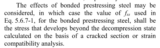
Another wrinkle is this following paragraph from AASHTO, which I don't quite understand and which seems to me to contradict the above definition of fss as for non-prestressed reinforcement.

Capture2_mknp9q.png
 
Replies continue below

Recommended for you

Disclaimer: I'm not a bridge guy and I've only given this a cursory look.

In general, unbonded PT isn't great for crack control. It tends to produce larger cracks spaced relatively far apart. This, in contrast to what we usually want with crack control: small, closely spaced cracks. In the absence of bonded reinforcing, unbonded PT can even start to mimic tied arch behavior which is generally considered undesirable in flexural members. Unbonded PT will slip longitudinally relative to the surrounding concrete (says Cpt Obvious). As such, it doesn't share the strain condition of the surrounding concrete locally.

All this may be why unbonded PT isn't being counted as beneficial for crack control and an exception is available for bonded PT.

If someone more convincing show up there, run with their answer.
 
KootK, thanks for the background info. That all makes sense. Now I guess to restate my question a little more simply - how do I go about calculating fss in a beam with bonded prestressed reinforcement as well as bonded regular reinforcement?
 
BE21 said:
Now I guess to restate my question a little more simply - how do I go about calculating fss in a beam with bonded prestressed reinforcement as well as bonded regular reinforcement?

Per that second blurb that you posted I would guess.
 
I'm not sure if I fully understand that second blurb. Does it just mean fss = the stress in the prestress tendons at service loading? Should it include effects of long term losses?
 
I would be inclined to take it as the prestress in the tendons at service, including long term losses, less the stress in the tendons when the tension face concrete first goes into tension (decompression state).
 
I might be completely wrong here, but I'm going to go down to the most basic principles of concrete design in hopes that it works in this case as well. Shouldn't the stress in nonprestressed reinforcement be the same as if you had an ideal section loaded with bending moment and axial prestress (this is the part of your second picture that says "on the basis of a cracked section")?
If I'm not mistaken picture below should be the way to do it. Note tha "n" is the ratio of steel to concrete modulus of elasticity including creep and I did not care for the "-1" on the compression side.
001_co6gly.png

This means that when you plug in the geometry, steel area, loads and steel stress limit sigma1 you should get the height of the compression area... from there it should be fairly easy to get all the other stresses (in concrete and compression steel) and ultimately you should be able to get the bending moment that causes said stress.
If your service load moment is lower than the one that you calculated - stress in the nonprestressed steel should be fine.
Other option if you need the stress for a specific bending moment is to iterate height of the compression area to get the stress at a specific bending moment.
 
KootK said:
I would be inclined to take it as the prestress in the tendons at service, including long term losses, less the stress in the tendons when the tension face concrete first goes into tension (decompression state).

A few questions on this:

1. So to make sure I understand correctly, this would mean fss = (the actual final stress in the tendons) - (the minimum prestress needed to eliminate tension at the tension face due to service loads)?

2. I realize I left out something significant from the AASHTO snippet. s is defined as "the spacing of non-prestressed reinforcement in the layer closest to the tension face". My prestressing tendons are spaced vertically along the height of the beam. So say I calculate fss in the bottom tendon and plug it into this equation - then what is the meaning of s?


rapt said:
Why would the bars below the PT ducts be yielded according to a strain compatibility calculation under service loads?

In the specific case I'm working on, dead load is quite high in comparison to live load. So service moment is not far off from ultimate moment. So the original method in this spreadsheet of checking stresses in the non-prestressed reinforcement ignoring the presence of prestress even under service load shows the reinforcement far beyond yield point.

I think I was envisioning the strain compatibility incorrectly when I made my first statement, but I'm still confused on how to work it out. Since the tendons are in tension and the surrounding concrete is in compression, does that mean strain compatibility shouldn't be applicable? Does it mean the bottom non-PT reinforcement is also in compression?

hardbutmild said:

I think I'm not quite understanding what you're doing. Once prestressing is applied, the entire beam is in compression, so wouldn't that mean x = d? And why does the PT resultant as you show it coincide with the bottom of the compression zone?
 
BE21 said:
1. So to make sure I understand correctly, this would mean fss = (the actual final stress in the tendons) - (the minimum prestress needed to eliminate tension at the tension face due to service loads)?

Yes, that's how I see it. The stress present in the tendons prior to cracking may well delay the onset of cracking via member recompression. But, once cracking occurs, the pre-cracking tendon stress doesn't do much to help keep cracks small and well distributed. That's why we're interested only in the change in tendon stress that occurs after initial cracking. Let me know if I'm now drowning you in superfluous commentary.

BE21 said:
2. I realize I left out something significant from the AASHTO snippet. s is defined as "the spacing of non-prestressed reinforcement in the layer closest to the tension face". My prestressing tendons are spaced vertically along the height of the beam. So say I calculate fss in the bottom tendon and plug it into this equation - then what is the meaning of s?

I would think that the meaning for would be the same for the prestressing tendons as it would be for mild rebar: the horizontal spacing of the reinforcement. The idea is that any one element of reinforcing only restrains cracking over a modest width of the tension face. So tightly spaced reinforcement does the job better. I can imagine that this aspect sometimes makes it difficult to use prestressing as crack control reinforcement, particularly if the reinforcement were draped such that it was quite far from the tension face at some cross sections.
 
Thanks KootK, your explanation for point 1 makes it very clear for me now.

Regarding point 2, I think this may bring me back full circle. I am planning to count on the non-prestressed reinforcement as crack control, not the PT. So doesn't it make sense in that case to use fss in the non-PT reinforcement after all? And if the whole section is in compression due to the PT, then there is no tensile stress in the rebar, fss = 0, and the crack control check is not even relevant. Do you agree with this logic?
 
Kootk,

It is normally taken as the change in stress in the steel from decompression of the concrete at the level of the steel to the stress under the service load. This applies to any bonded steel layer.
 
BridgeEngineer21 said:
I think I'm not quite understanding what you're doing. Once prestressing is applied, the entire beam is in compression, so wouldn't that mean x = d? And why does the PT resultant as you show it coincide with the bottom of the compression zone?

If the entire beam is in compression why would you check crack control? There are no cracks! What are you controlling? As others mentioned you need the difference of stresses... what difference if the element remains uncracked?
I assumed that some level of decompression exists (I don't know the english term, but we call it "partial prestressing"), so part of the section is in tension.
PT resultant does not coincide with the bottom of the compression zone, it just looks like that because I'm not very good at drawing. The PT force acts at the centroid of the section (if it is lower, you can place it in the centroid and add the resulting moment to M).
What I did is a classic solution for SLS - you make an ideal section and act as if it was completely concrete section acting elastic.

BridgeEngineer21 said:
Does it mean the bottom non-PT reinforcement is also in compression?
If the whole section is in compression - yes.

I honestly do not understand this discussion, isn't this related to NONprestressed reinforcement?

BridgeEngineer21 said:
I am planning to count on the non-prestressed reinforcement as crack control, not the PT.
To me, this is the only logical approach.
 
Thanks hardbutmild. I was pretty mixed up when I started this thread, but I think I've gotten it straightened out now:

-If the beam is fully in compression, crack control is irrelevant and not checked

-If there is some small amount of decompression at the bottom flange of the beam, I would check crack control using non-PT reinforcement only. In that case, I should use strain compatibility to get the stress in the bottom reinforcement and take that as fss. If the tension zone is small, the reinforcement is most likely not close to yielding.

-Of course the most conservative thing to do for crack control is still just to assume a stress of 0.6fy exists in the bottom bars, regardless of the actual situation, and space them accordingly.
 
No matter what the case, the bottom reinforcement should never be near to yielding under service loading for any concrete flexural section, RC or PT.

If it is yielding or even near yielding at service loads, there is either something wrong with your strain compatibility methodology or something wrong with the design.
 
rapt said:
Kootk, it is normally taken as the change in stress in the steel from decompression of the concrete at the level of the steel to the stress under the service load. This applies to any bonded steel layer.

Thanks for that clarification rapt.
 
Status
Not open for further replies.
Back
Top