Continue to Site

Eng-Tips is the largest engineering community on the Internet

Intelligent Work Forums for Engineering Professionals

  • Congratulations IDS on being selected by the Eng-Tips community for having the most helpful posts in the forums last week. Way to Go!

Crack in A485-1 ring during plug quenching 1

Status
Not open for further replies.

HaranSR

Materials
Aug 17, 2017
15
I am facing quench cracking during plug hardening of ring with oil quench (`40C).
Hardening temp at 830C. Ring is transfered to plugging press and quenched with oil.
Material is A485-1, ring dia is 250mm and thickness is 23mm.
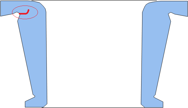
Crack always in the same location of undercut. Any reasons / solution ?
 
Replies continue below

Recommended for you

Pictures please!

"Even,if you are a minority of one, truth is the truth."

Mahatma Gandhi.
 
You need a metallurgical evaluation of the component from a reputable lab. I do not share speculation in such a case without getting the data in an examination, which includes testing.
 
We have done all the metallurgical tests
No decarb / recarb
Fine martensite
Grain size 8 or finer
No any segregation
No GBO / NMTP
Hardness - 64 HRc as quenched both core and surface.
 
Sounds like this ring is intended for a rolling element bearing race. A sketch of the ring cross section and undercut would be helpful. Also a sketch showing how the quench die interfaces with the ring, including any oil flow paths provided, would be good.

Is the quench die possibly restricting oil flow to the undercut surface?
 
Hi tbuelna yes you are right.
Sketch_1_eaxugz.png

Quench die is not restricting the oil flow to the undercut. Undercut is open to oil.
I have shown a small sketch for understanding. And crack always on the top undercut area.
Die is a taper die which sits on both top and bottom bore. Oil flow is from both top and bottom.
 
Of course the crack is always at the top undercut area. All things equal, failures always occur at the weakest point, which in this design would be at the top undercut. That does not necessarily mean it is a design issue though. Again, you need more than just the testing you did - you need actual failure analysis from someone experienced in the process.
 
Without a sketch of how the quench die(s) constrain the bearing race, how the oil flows over the race surfaces, it's hard to offer potential solutions to resolve your fracture problem.

In general quench cracks often occur where there is a significant local difference in heat transfer and cooling rate. The re-entrant profile of the grinding relief might be creating a separated recirculating local flow condition preventing the cool bulk oil flow from reaching the obscured undercut surfaces, thus inhibiting local heat transfer significantly. Also, the radial section is thick below the undercut, the flange above the undercut is even radially stiffer, and the narrow undercut groove between with its relatively small root radius provides a very effective local stress concentration.

Might be worth spending some time on modeling to optimize the cooling oil flows and heat transfer of your quench tooling.
 
Thank You tbuelna, will try to make a sketch of die and send as soon.
Thanks
 
Hi tbuelna can you please share your email id.
 
Hi one more information parts with out undercut also is cracking the same way.
What's your opinion on this?
 
If you don't want to pay for the paper I referenced in my previous post, you can type "Understanding Process Sensitivities in Press Quenching: an integrated Approach" into Google and then click on the first link that comes up with a pdf file of that title. The paper will download for free.

Maui

 
Thank You Maui. I have downloaded the paper will spend some time to read now.
Thanks again.
 
Oh Thank You Maui nice paper & good informative.
What will happen if we take out the parts from quenching at slightly higer temperature (may be at 100C surface temperature instead of 50C).
So martensite formation in the core can be made uniform with the surface at the end.
Will this help.
 
Haran, based on what you have told us, it appears that the crack is forming at a stress concentration located in the undercut. You should make the radius in this location as large as the design will allow. The oil flow in this same area will very likely be reduced due to the formation of a vapor barrier that is trapped in the undercut because of the geometry and the manner in which you have chosen to orient this part during quenching. I would suggest that you flip it upside down from the orientation you have provided. When a vapor barrier forms during the initial stage of quenching it will not be locked into position in the undercut if you do this. Your oil flow rate around the part should also be carefully selected so that the entire cross section transforms to martensite, but the oil flow rate should not be so fast that cracking occurs. What is the oil flow rate that you are currently using? The pulsing capability on the quenching machine should be activated. Have you been using pulsing?

Maui

 
Haran, I would not recommend taking the parts out of the oil prematurely so that they are at a higher temperature than the oil. A better approach would be to slow down the quench by reducing the oil flow rate. But in order to make any recommendation regarding what oil flow rate is appropriate, I need to know what rate you are currently using.

Maui

 
Hi Maui we have already tried by flipping the part upside down but no use and parts still cracked. Bottom oil flow is 300 LPM (this is to quench bore) and top flow 350 LPM (to quench OD) In our quench press we do not have pulsing facility.
Do you suggest to reduce the oil flow and what is your recommendation.
Thanks
 
Several changes are required to reduce the severity of your problem, and one of those changes should be flipping the part as recommended. The second change is to increase the radius of curvature at the stress concentration where the crack is forming. The third change is to reduce your oil flow rate by 50%. If you had pulsing available I would also recommend that you activate it. Pulsing in these situations is often critical, and without it you may not be able to completely eliminate this problem, although implementing the other changes will help improve the situation.

Are you measuring the temperature of the parts as they come out of the quench? What is their average temperature?

Maui

 
Exit temp is 50 C.
Quench time is 160 Sec.
Ok let me try with reduced flow rate.
 
Status
Not open for further replies.

Part and Inventory Search

Sponsor