Continue to Site

Eng-Tips is the largest engineering community on the Internet

Intelligent Work Forums for Engineering Professionals

  • Congratulations KootK on being selected by the Eng-Tips community for having the most helpful posts in the forums last week. Way to Go!

crane runway beam column seat connection bolts 1

Status
Not open for further replies.

doganarslan

Structural
Nov 9, 2015
5
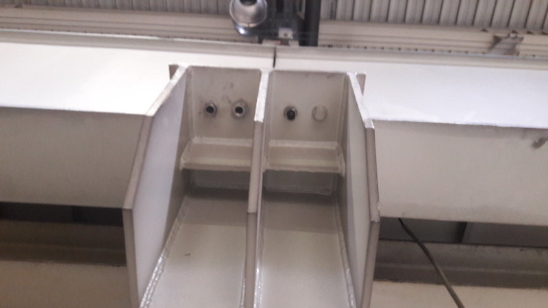
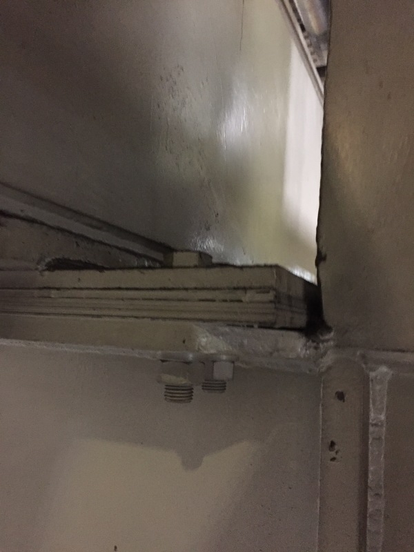
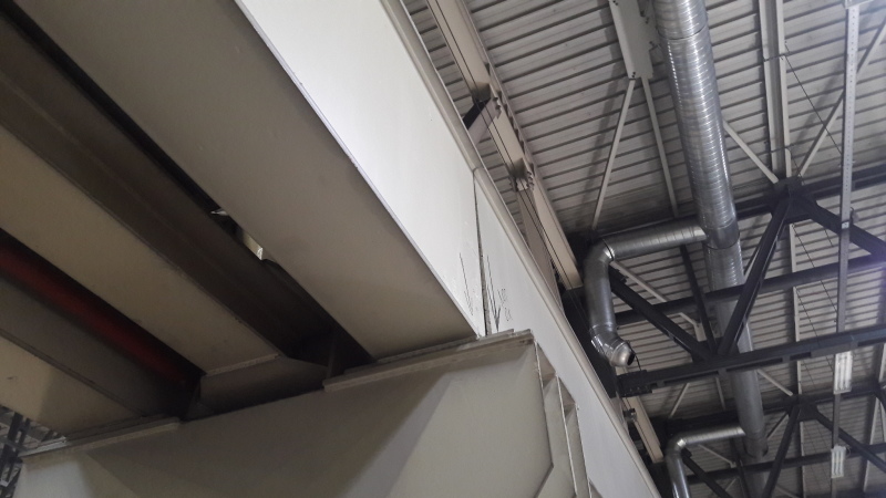
As seen from the attached photos (pic-1 and pic-3) some of the crane runway beam bolts ruptured and runway beam bottom side moved.
This problem occur only in one beam connection and same connection detail used along the facility.
I need to find out the reasons behind this problem and since yesterday I found several alternative reasons as I mentioned below;

- fatigue. (but i don't why only this one not the others.)
- some bolt clearances of 'this' produced plate is different from the attached detail and so several bolts worked alone for runway beam dynamic loads.
- lateral torsional buckling has occurred and lateral force at bottom flange ruptured the bolts.
1_nis7zx.jpg

2_ovpdiz.jpg

3_jux9xs.jpg

IMG_4810_l65nae.jpg


Any reasons else?

Thanks,

Dogan.
 
Replies continue below

Recommended for you

My first thought is to check the bolts for proper tightening. If they are not preloaded to prevent slipping, you could easily have one bolt taking the load in shear. As that bolt fails, the connection slips until the next bolt is in bearing. It cannot take the entire load and it fails, this process repeats until all the bolts have failed.

Looking at the bottom photograph, it doesn't appear the shim pack is fully compressed which would support the possibility the bolts were not installed and tightened properly.

The second photo from the top seems to indicate the bolts were not the correct length, thus there is less engagement than the full nut.

The top photograph appears to show the wrong type of fasteners were used.

Best regards - Al
 
Untitled_ah5w9p.jpg


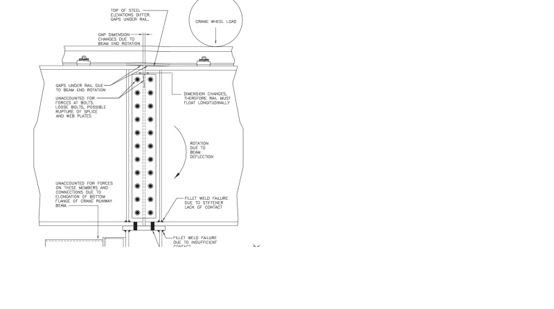
It is not a good design per the circled connection in the pdf file. The configuration restraints the crane beam end from rotating, and therefore the bolts or the crane beam will experience fatigue damage. Of course, it also depends on the crane work class. The connection may be not critical for light work class crane. And there is no lateral supports on the top flange of crane beam ends. For your information: “Crane-supporting steel structures - design guides” gives some example how to setup the crane connection.
 
Bolt slots appear to be too large for the bolt size. Also it looks like a mixture of machine screws and bolts...not high strength structural bolts.

Use properly sized high strength structural bolts and pre-tension them.
 
Find out how the crane has been used. At our electric generating stations it is common for a crane to be used daily on a short section of the runway near a delivery bay, but only occasionally on the long sections of the same runway over the turbine-generators. A use pattern like this could explain why failure is being seen at only one location.

[idea]
[r2d2]
 
any chance the bolt holes could have been field adjusted for fit up using an oxyacetylene torch hole stretcher? As Ron noted, they should be pre-tensioned for a slip critical condition.

Dik
 
I notice from your PDF drawing that the crane girder is made up of 2-spans @ 8m each, continuous spans.

Capture_icswrx.png


With continuous crane girders it may be possible that your end-span connection bolt failures are due to tension forces when the crane is in the opposing/adjacent span, causing fatigue effects in the connection.

To troubleshoot the probable-cause it may be worthwhile to up-close visually observe the end-connection when the far-span of the crane girder is traversing under load.
 
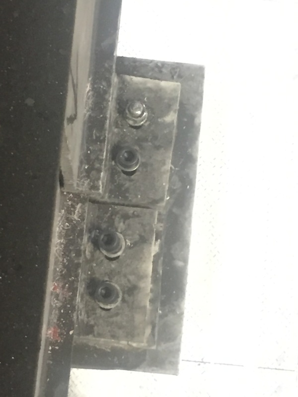
I can't figure where the bottom picture is taken. It doesn't seem to be at the location where the bolts failed, and unless my eyes deceive, there appears to be a chunk of steel missing to the right of the nuts.
 
hokie66 said:
I can't figure where the bottom picture is taken. It doesn't seem to be at the location where the bolts failed, and unless my eyes deceive, there appears to be a chunk of steel missing to the right of the nuts.

I think that last photo is at the interior support of the 2-span crane girder condition, at inside face of the girder, adjacent to the building column (which is on the extreme RHS of that photo).
 
If that is the case, there seems to have been a big whack between the beam bearing plate and column at that point.

Columns in industrial buildings get a lot of abuse. Has there been impact damage at the column bases? This could have resulted in twisting the crane beam bracket.
 
Ingenuity said:
I think that last photo is at the interior support of the 2-span crane girder condition, at inside face of the girder, adjacent to the building column (which is on the extreme RHS of that photo).
yes, it is other side of the beam. I uploaded it to show they used shim plates to level the beams. It was impossible to see bottom of the plate with problem that day.

dik said:
any chance the bolt holes could have been field adjusted for fit up using an oxyacetylene torch hole stretcher? As Ron noted, they should be pre-tensioned for a slip critical condition.
I did not saw any torch touch Dik. The 3 bolts that you saw on the picture are just temporary ones. They will be changed to preloaded ones as you mentioned.

Ron said:
Bolt slots appear to be too large for the bolt size. Also it looks like a mixture of machine screws and bolts...not high strength structural bolts.

Yeah, the M24 slotted hole dimensions(25x48) bigger than short slot hole dimensions(27x32) and smaller than long-slot dimensions(27*60) mentioned at AISC 360 Table J3.3M. But I can't say this is the main problem?
 
Hard to tell in the picture but did they fail in tension or shear? I think It's ts possible that the failure occurred from over-tightening of the bolts. From the research I've done, it's typically recommended that these bolts be finger tightened for the reasons Shu Jiang mentioned. I have also recommend nylon stop nuts in conjunction with the hand tightening to prevent the bolts from coming loose. However with the slotted connections you need to make sure your in plane lateral force is resolved, so slip critical connections might be required here.[pre][/pre]
 
Status
Not open for further replies.

Part and Inventory Search

Sponsor