Continue to Site

Eng-Tips is the largest engineering community on the Internet

Intelligent Work Forums for Engineering Professionals

  • Congratulations KootK on being selected by the Eng-Tips community for having the most helpful posts in the forums last week. Way to Go!

Crash Test Query 1

Status
Not open for further replies.

Sriddle

Automotive
Jul 9, 2024
5
Hi all

I am currently designing an aluminum frame for the rear of a truck bed.
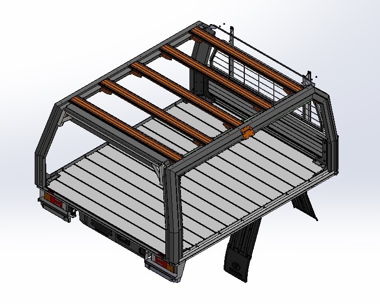
Truck_Bed_opku9a.jpg


The frame will be load bearing and have a dynamic rating of 150kg. I have been asked to perform some 'crash testing' on the frame prototype. This requires a certain amount of force to be exerted on the assembly in a horizontal direction. See example here of a roof rack test performed on a track (
I do not have access to a track or testing facility so was wondering if there is a good way to perform a bench test via pulling on the assembly using a winch or similar device.

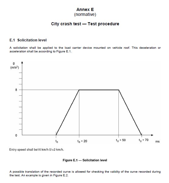
What sort of calculations would you recommend to determine the correct load or force? The testing standard ISO11154 states that the load has a force of 8g applied to it and is tested to 1.5 times the stated capacity.
ISO11154_v7bjdk.jpg


Sorry if this is a tad vague, as you can probably tell I am not a structural engineer, merely a lowly CAD monkey! :)

Any help would be appreciated.

Steve
 
Replies continue below

Recommended for you

Um. The y axis is labeled as g (m/s2). 1g is 10 m/s2. So is 8g, or 8 m/s2? If it is a crash the higher figure is more likely.

50 ms makes it a dynamic event, your frame is going to have modes starting at 10-20 Hz or so. If you just apply 80*(mass of tray+mass of cargo) to the cg, with boundary conditions at the fixtures you'll get lower stresses than if you apply a dynamic pulse to the bed of the frame which is far more realistic.

Is there anyone at your company who has experience with this stuff? Crash modelling is hard.


Cheers

Greg Locock


New here? Try reading these, they might help FAQ731-376
 
Yeah, the math is off, and/or the label on the graph is wrong. 16 km/hr is equal to 4.44 m/s, and the velocity goes to zero in some .05 seconds (averaging the two triangular bits), dv/dt = 89 m/s^2, or about 9 g's of deceleration, still not the 8 g's quoted but close.

edit: the label on the y axis of the graph is definitely wrong, in that it's using two unequal units (g's and m/s^2). I'd guess based on the 16 km/s and pulse duration that g's is more correct-er.
 
1) Are you sure this is the same crash test? Your device looks like it forms part of the structure of the vehicle?

Where are the fixing points?

what loads are going to be imposed on it in a crash?

Is it just a frame?

but a crash test is a crash test, not a static load test.

You could mount it on a vehicle and have it reverse at 16km/h with some strong ropes / chains attached to the front and then see what happens?

Remember - More details = better answers
Also: If you get a response it's polite to respond to it.
 
I would guess it is a frame bolted to the chassis or tray of a 1 tonne ute (Ranger, Troopie or whatever). Usually the bolts will be vertical down to brackets on the rails.

Cheers

Greg Locock


New here? Try reading these, they might help FAQ731-376
 
Hi all

Thanks for the replies.

'50 ms makes it a dynamic event, your frame is going to have modes starting at 10-20 Hz or so. If you just apply 80*(mass of tray+mass of cargo) to the cg, with boundary conditions at the fixtures you'll get lower stresses than if you apply a dynamic pulse to the bed of the frame which is far more realistic.' - is there a way to estimate the forces of the dynamic load?

Unfortunately no one else in the company with crash test experience. I have contacted some third party testing facilities but budget does not allow for this.

I am curious as to whether I can estimate the loads generated in the dynamic test and then simply apply a load similar to that (in a much slower fashion). I have a physical prototype which I can use for destructive testing.

Screenshot_2024-07-11_093929_hsurom.png


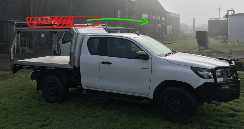
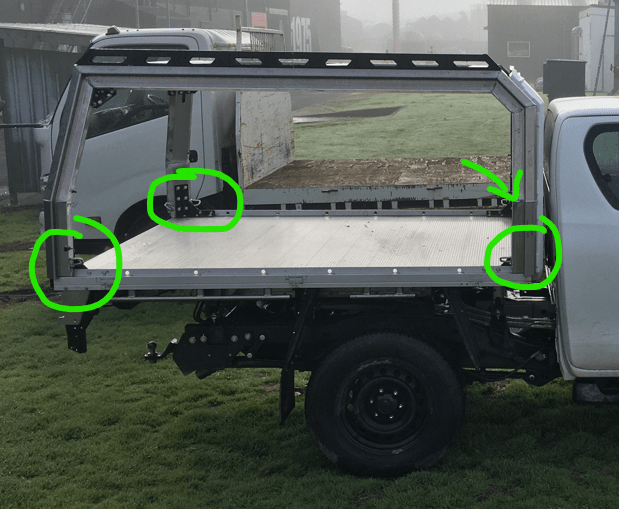
The frame is bolted down through the aluminum flat deck using two 5mm thick steel brackets on each foot. The aluminum flat deck is sandwiched between the steel brackets. The frame and flat deck will be removed from the vehicle and bolted to the ground for testing.

...essentially I am trying to figure out if I can create a test that would mimic the results of the dynamic test using basic workshop equipment.

Steve
 
Hi LittleInch

1) Are you sure this is the same crash test? Your device looks like it forms part of the structure of the vehicle?

Where are the fixing points?- the device is the upper frame assembly. Fixed in each corner using a series of 5mm thick steel brackets.

Screenshot_2024-07-11_094923_dxzblm.png


what loads are going to be imposed on it in a crash?- 225kg at 8g

Is it just a frame?- the frame is the structural component. It does have thermofomed ABS doors but these wont be included in the test.

but a crash test is a crash test, not a static load test.- I am aware of this, but I am trying to figure out if its possible to create a new test that would provide a similar result. Limited resources are the issue here.

You could mount it on a vehicle and have it reverse at 16km/h with some strong ropes / chains attached to the front and then see what happens? I like your thinking! Not sure the owners of the vehicle would approve :s
 
OP,
What are your math and mechanics of material skills like? I've known CAD monkeys who were better designers than a lot of engineers I know, that said, I've known some who couldn't peel and banana. (Back of a napkin calcs) I think you can replicate the acceleration - deceleration with springs or combination springs and air actuator and your rack being mounted to a dolly/cart of some sort. If it's only the acceleration - deceleration that needs validated and the 16kph and other velocity requirements are allowed to be negated, then I think this is possible.
 
I don't know how it works in kiwiland but in Australia you have to work with a compliance engineer who will advise you on what needs to be done.

In the absence of that, apply a factor of ignorance of 3 and use a static test. It will be less meaningless than a dynamic FEA where you don't have a model of the car and don't have experience with crash testing.

Cheers

Greg Locock


New here? Try reading these, they might help FAQ731-376
 
sriddle said:
I have been asked to perform some 'crash testing' on the frame prototype.
Asked by who?
Why?

The testing standard ISO11154 states
Have you read and understood the entire standard?
Are you sure that this standard applies to your rack?

but budget does not allow for this.
Limited resources are the issue here.
Do you have the budget and resources for the potential liability that you're taking on? Especially if you can't provide objective evidence that you designed and tested according to some accepted standard?
Assuming that this will be a "product", have you had a discussion with your insurer?

I am trying to figure out if I can create a test that would mimic the results of the dynamic test using basic workshop equipment.
No, you can't. If that were possible then the nice people that developed the ISO standard would have defined only static load tests. In fact, they defined a sequence of tests that includes both static and dynamic (crash) tests, and others. Again, have you read and understood the standard?

Greg said:
Crash modelling is hard.
Yes, it is. It requires specialized software, and generally multiple rounds of simulation and validation by test to confirm that your modeling techniques match reality before you gain enough confidence to use only analysis. If you don't have the budget for one test then you certainly don't have the budget to do this properly.

LittleInch said:
You could mount it on a vehicle and have it reverse at 16km/h with some strong ropes / chains attached to the front and then see what happens?
Please don't do this.
 
Heaviside- unfortunately I fall into the 'struggle to peel the banana' category.

I don't know how it works in kiwiland but in Australia you have to work with a compliance engineer who will advise you on what needs to be done.
Depends who we are dealing with. If we are working with OEM customers they will hold our hand throughout the process. In this case its an aftermarket accessory and as far as I can tell the regulations in NZ are pretty lose.

Chances are we will end up loading it up as you suggest with a massive margin.

MintJulep- all great questions! Many which I have asked myself already. I don't think that the standard is applicable to this product but its the closest thing we have from ISO standpoint. I don't agree with this approach but some people like the fact that they can attach a standard to the report. As per above, I think ill just hook up a load cell and give it hell. Very scientific I know.

Thanks for all the comments and suggestions.
 
some people said:
some people like the fact that they can attach a standard to the report

Claiming compliance to a standard without actually following the standard to demonstrate compliance is fraud.

Even in NZ with its pretty lose regulations.
 
Thinking about it the factor of ignorance for lifting gear is 10, that is we design for 10 times the hoist load, and annually inspect (real test) to 4. As I have pointed out many times, this means the majority of the fatigue life of the system is expended in its annual safety test.

Cheers

Greg Locock


New here? Try reading these, they might help FAQ731-376
 
OP,
I guess I misunderstood your goal. I was under the impression that you were validating a prototype.
Sriddle said:
I don't agree with this approach but some people like the fact that they can attach a standard to the report.
I agree with MintJulep that claiming that it meets a standard without doing the testing would at the very least be unethical and could even be criminal. Before I comment further, I have some questions.
Are there regulations requiring your company to build and test the rack to meet ISO-11154?
Are there regulations requiring the racks like these to meet ISO-11154 if installed on a vehicle?
Are these racks being designed and fabricated for a company who will in turn, be testing them to ISO-11154?

If your only claim and validation is to say that these racks were tested via destructive testing and withstood an acceleration - deceleration cycle of 8g in .4ms, then, this can be done. Load cells are not going to get you there, you need accelerometers. The rack will need to be mounted to something that moves in a linear fashion, i.e., a rail system, a dolly/cart. If you don't have accelerometers, then possibly these. As far as the load source, I was thinking springs or actuators but even a pendulum and weight might work, I doubt, just a person shaking it, would some close. The goal will be 8g or higher of impact/shock/acceleration - deceleration in .4ms or less. Both conditions (acceleration and time) need to be met.
 
Sriddle,

I think that you are in fact in quite a dangerous place with this device.

From what I can see this is basically a framework designed to fit on a flat deck or perhaps include the flat deck - I don't really know what's "original" and what is your contraption. It also appears to have roof rails on ot so that, as you show on your pcture, you can stick on roof bars or roof boxes or whatever like a normal car.

The potential for serious injury is twofold.
One - in a collision this framework and what ever is inside it or on top of it rips itself out of it mounting and comes off and hits someone
Two - It does the same thing but crushes the cab from behind or allows the roof bars to come off and do the same thing.

doing something for yourself where you take the risk is one thing and doesn't negate item one, but if you're trying to sell this to the general public, then trying to cheapskate around the testing requirements is simply going to put you in deep trouble in the inevitable event of a collision. So I think you might need to do a bit more serious consideration here about what it is you're trying to do. IMHO.

Remember - More details = better answers
Also: If you get a response it's polite to respond to it.
 
Probably the 10 stacked ladders the painters transport with a few bungie cords will become the projectile long before this will.
 
Assuming that this is just a cargo rack:
I see where LitteInch is coming from but I would tend to agree more with XR250 in this case. The random parts you have half heartedly attached will cause more concern in a wreck than the rack itself. You would have to make some assumptions about your G's but some pretty basic shear/moment calculations with a generous safely factor should be enough to make sure it will stay attached in the event of a collision. It looks to me like it may be aluminum, but even in the case of it being steel it is still a relatively minor structure, I wouldn't get too concerned about it causing a major cabin failure in an accident.

Let's say you rate this to carry 200KG. I would design and physically test it with 600-800kg in a vertical compression test, as well as being loaded in all of the directions that it could see that force while the vehicle is off camber, like while climbing a slope on a trail. If your vehicle will tip anyway at 40 degrees, I would test your 800KG load being applied at a 40 degree angle. Should the vehicle be involved in a major accident, it's just a roof rack, write it off and call it a day.


If you are advertising this as a structural safety cage:
I would agree with most of the others in that there is no way in which you will be able to accurately simulate the force loads from a collision. The liability is far to high to not have 100% accurate testing with something that is supposed to be providing some level of safely.
 
Morning all

Thank you for you comments, concerns and recommendations. Its been very helpful.

As a result we will perform the quasi static load tests in house and outsource all dynamic testing.

Cheers

Steve
 
Status
Not open for further replies.

Part and Inventory Search

Sponsor