Continue to Site

Eng-Tips is the largest engineering community on the Internet

Intelligent Work Forums for Engineering Professionals

  • Congratulations MintJulep on being selected by the Eng-Tips community for having the most helpful posts in the forums last week. Way to Go!

Create Instance with different materials without using TIE Constraint

Status
Not open for further replies.

MWicke

Mechanical
Feb 25, 2016
5
Dear all,

I have two different volumes, an inclusion and a cylindrical volume, which consist of two different materials. The inclusion should be insert in the cylindrical volume, that means the two parts should act as a single volume upon loading to analyse the stress concentration.
My idea was to define different materials / section assignments in the part modul and then use merge with retained boundaries to create one instance, so I can mesh the two volumes as one without using tie constraints.

However, preparing a data check, I get lots of warnings concerning tie constraints although I didn't define any constraints (see attachment with warnings; the 8783 nodes in the first line are the nodes along the retained boundaries).
The results were plausibel, but does this mean that I have to define tie constraints?! If so, what's the best way to create tie constraints - use cut in the assembly modul to create a "hole" with the shape of the inclusion in the cylinder and then insert the inclusion per merge?
 
 http://files.engineering.com/getfile.aspx?folder=9d707d95-33c4-4c68-b225-a3f910818e70&file=Warnings.JPG
Replies continue below

Recommended for you

Can you share your CAE file?

Did you create the constraints before merging? They may have been carried over as intelligent as Abaqus can when you merged. Imagine if you have a fixed face then merge 2 parts the face should probably still be fixed.

I hope this helps.

Rob

Rob Stupplebeen
Rob's Engineering Blog
Rob's LinkedIn Profile
 
Abaqus automatically creates the constraints, but I don't know when and why.

In my opinion the problem is, that I define the section / section assignment of the cylindrical volume using "region". This means the faces of the inclusion are involved in the section assignment and then, defining also a section assignment for the inclusion, there is an overlap. Is this possible and how could I avoid the overlap?!

My CAE file is to big. However, I created a python script, which generates my model without the sections / section assignments. You just have to edit the path to the inclusion in line 49. Maybe this helps finding the mistake in my procedure.
 
 http://files.engineering.com/getfile.aspx?folder=cfe90e83-d655-4f86-b738-3d90bdb2b607&file=Modelling_Inclusion.zip
I made the change to line 49 but it has an error saying that the IGS is corrupt. I did import the IGS by hand without issue though. On your CAE file can you try compressing the MDB? Also, deleting the mesh then compressing may make it small enough.

By the way what is this? The IGS looks very odd?

Thanks.
Rob

Rob Stupplebeen
Rob's Engineering Blog
Rob's LinkedIn Profile
 
In the attachment my CAE file (created with ABQ 6.14-2) with the whole Model except from the sections / section assignments. The merged part is name "InclusionInCylVol".
I hope it works.

The IGS is an inclusion obtained by X-ray CT. For importing in Abaqus as a volume, the inclusion was reconstructed in a reverse-engineering process. That is the reason for the initial partitioning on the surface. However, using virtual topology, the "patches" on the surface are removed later.

Thanks!
Marcel
 
 http://files.engineering.com/getfile.aspx?folder=ee27f789-9a4c-4d94-995d-fb2112beb680&file=Modelling_Inclusion.cae
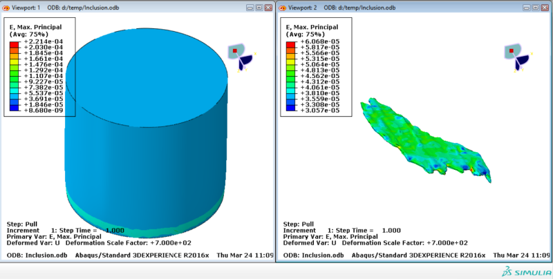
I'm using Abaqus 2016 so I have uploaded the INP file instead. Here are the steps that I did.

1. Deleted merged solid and emptied the assembly.
2. Added both solids to the assembly.
3. Translated the inclusion 1 unit down.
4. Merged instances deleting the original and retaining the boundaries.
5. Tet meshed with default seeding.
6. Boundary condition 'FixBottom' only constrained in 1 direction changed to all 3

I hope this helps.
20160324111346-OPTIMAL-ROB_mb8nfe.png


Rob Stupplebeen
Rob's Engineering Blog
Rob's LinkedIn Profile
 
Status
Not open for further replies.

Part and Inventory Search

Sponsor