Continue to Site

Eng-Tips is the largest engineering community on the Internet

Intelligent Work Forums for Engineering Professionals

  • Congratulations KootK on being selected by the Eng-Tips community for having the most helpful posts in the forums last week. Way to Go!

creating a reference planes/axis system in catia assembly

Status
Not open for further replies.

lcatg

Mechanical
Oct 7, 2015
41
Hi,

how to position first component properly so that when front,side,top vies are taken part is alligned properly? while repositioning i rotated the component and now i dont know how to adjust as there is no reference plane/axis system to give constraints?pls find the attached image. when side view is taken view is not right.
 
 http://files.engineering.com/getfile.aspx?folder=efaf6f46-5c73-4056-8d51-2c0047da24da&file=Capture.PNG
Replies continue below

Recommended for you

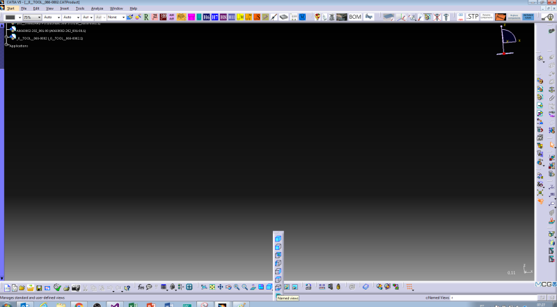
You can define the views as you want.
named_views_zyqtv6.png


After this, select the view that you want to reorient, and click properties icon. Then orient it as needed.
You can skip this, by moving the component. For that use the compass.

Tiago Figueiredo
Tooling Engineer

Youtube channel:
 
I am new to catia, so its difficult to follow your method with that minimum detail. But i found a new way, create a dummy part, fix it in assembly and use its planes to position the first component.
 
Linges; that's the way I do it too.

But I have a few extra steps:
1. Insert a new part, and immediately fix it
2. apply a coincidence constraint between the axis of the new, dummy part and the axis of the first component
3. fix the first component
4. delete the coincidence constraint from step 2
5. delete the new, dummy part (it's no longer needed)

I discovered that it saves me alot of time and aggregation to always fix that first component as soon as I insert it into a new assembly.
 
Status
Not open for further replies.

Part and Inventory Search

Sponsor