Continue to Site

Eng-Tips is the largest engineering community on the Internet

Intelligent Work Forums for Engineering Professionals

  • Congratulations KootK on being selected by the Eng-Tips community for having the most helpful posts in the forums last week. Way to Go!

Creating wire fencing using NX 2

Status
Not open for further replies.

Atharva_Mechanical

Mechanical
Oct 31, 2023
5
Hi Everyone,

I was wondering if there is a better way to do what I am trying to do here.

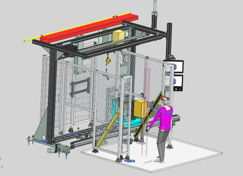
My intention is to create a wire mesh / fencing around this cell. I have the fabrication structure (unistrut) to mount this fence on (Please refer to the photo).
My basic approach is to create a cylinder of dia 3mm and pattern it to create vertical fence, and then repeat for horizontal fencing.
Initially, I created this mesh structure (as described above) all around the cell with the hopes of trimming the excess using Extrude Subtract. But apparently, NX treats the cylinders that I patterned as individual entities. So I could not select the patterns and extrude cut the parts that are not fenced.
Then, I tried Assembly Cut command. This approach worked, but it was too compute heavy so I had to abandon it.
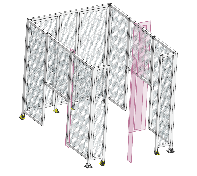
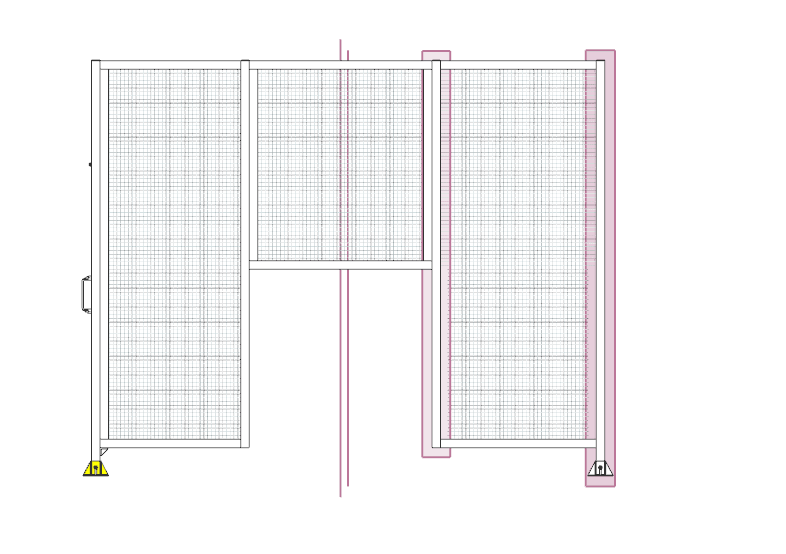
As a last resort, I created mesh (fencing with patterned vertical and horizontal cylinders) in the individual areas that I need fencing on. I didn't want to do it this way, but couldn't find any other better solution for it. Wasted a lot of time trying to troubleshoot this and find a better way to do this.

Any suggestions regarding better approach for doing what I did? My major issue was when Extrude Subtract wouldn't let me subtract the part of the fencing I created.

Thanks,
Best
Atharva D
Screenshot_2024-08-26_123606_uusied.png
Screenshot_2024-08-26_122800_h7c0ta.png
Screenshot_2024-08-26_123541_usqtum.png
 
Replies continue below

Recommended for you

If you would have done this back in the days on a drawing board with pen and paper,
would you then have drawn all the wires in these ?
You are spending time in creating something that doesn't add any value, unless the purpose is to render images.
The manufacturer will cut the wire fence the same way as a plate of sheet steel size x and y, he is not interested in the individual wires.

In case you still want to create this mesh, create the wire-s such that you can unite all wires into a single body. ( then remove the parameters...)
Then you can cut /unite etc .

Regards, Tomas

The more you know about a subject, the more you know how little you know about that subject.
 
I agree that this does not add any value in terms of drawing information/detail, but client wanted an isometric view that showed the fencing on the 2D layout of this cell.
One way I can think of for removing the parameter is creating a 2D sketch of the entire mesh and then extruding it by 3mm (or whatever is the thickness of the wire). But, that will result in wire mesh with square cross section, and not circular. I know I am being too picky about this when its not that big of a deal, but is there any other way to create the mesh with circular cross section without using patterns, so that the body of the mesh will be solid?

Thanks
Atharva D.
 
I've only had to make a safety fence like shown in your image once.

I did it old school though, before I knew what patterns were, if I recall correctly. I created planes for the outer boundary, made 1 line in X and 1 in Y where I wanted them, then trimmed them.
Then use Tube to create the wires, then what's now the legacy Transform and made rectangular array of each and united them.
It was time consuming, but the customer wanted a solid representation.

If I had to do it today? I'd probably goto Mcmaster.com and download a machine guard and modify if needed.

I thought I saw something on youtube a while back. when I searched today I found this chain-link tutorial...
 
There used to be a rendering material that simulated a mesh like this. Have not looked for this since the new material definitions were introduced.

If you still want to hava a mesh, do it the "dumb" way, no need for a parametric mesh.
Create a separate "mesh part".
In this create that "large mesh" by pattering wires.- larger than the largest "hole" you have in the assembly.
Make the wires such that they touch each other and can be united into a single body. Unite all.
-If they are united to a single body, the heavy hidden line calculations in drawing views is 50% done , else NX needs to calculate each junction in every view.
Remove parameters such that you end up with a single "body". ( Menu- edit-feature-remove parameters.) This will both remove any feature regeneration time and also make the file smaller in size.
Use this as a component in the assembly and either wave link it + cut to shape or use the Assembly Cut feature to cut into shape. ( this is why it should be larger)

Regards,
Tomas

The more you know about a subject, the more you know how little you know about that subject.
 
Nice use of the tube command there. I used tube to create first vertical and horizontal tube, then patterned it to the span. Then unite and then remove parameters. Now I have a dumb solid with mesh structure that I can trim / subtract. Thanks a lot guys!

Regards
Atharva
 
Status
Not open for further replies.

Part and Inventory Search

Sponsor