Continue to Site

Eng-Tips is the largest engineering community on the Internet

Intelligent Work Forums for Engineering Professionals

  • Congratulations KootK on being selected by the Eng-Tips community for having the most helpful posts in the forums last week. Way to Go!

CT wiring to Relay 2

Status
Not open for further replies.

budhiman

Electrical
Jan 26, 2016
60
Capture_iviyiy.jpg


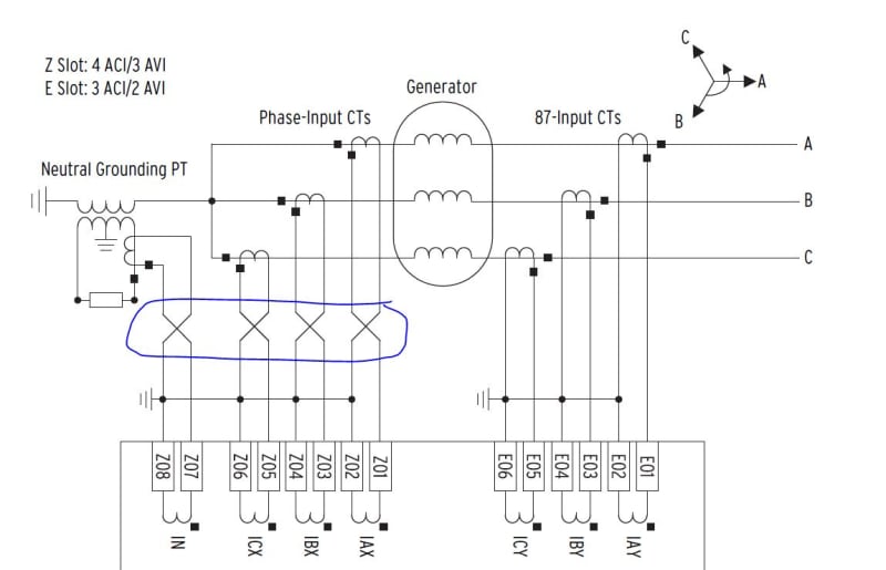
I had a question about the CT wiring to the relay shown in the picture. I was wondering is there a reason to show the wiring swapped other than connecting the polarity to the polarity input of the relay.
 
Replies continue below

Recommended for you

Isn’t that a good enough reason? The X side and the Y side have to be opposite polarity.

I’ll see your silver lining and raise you two black clouds. - Protection Operations
 
Dear Mr. budhiman (Electrical)(OP)
"...I had a question about the CT wiring to the relay shown in the picture. I was wondering is there a reason to show the wiring swapped other than connecting the polarity to the polarity input of the relay."
1. It is essential to follow the wiring and also the earthing point. DO NOT make any changes!
2. Observe the CT polarity (see the dot notation)
3. For example: a) Phase A phase-input CT MUST terminated on Z01,Z02. The other phases to follow the drawing strictly.
b) Phase A 87-input CT MUST terminated on E01,E02. The other phases to follow the drawing strictly.
Che Kuan Yau (Singapore)
 
Many relays will allow you to adjust polarity in the settings. I prefer to get the wiring correct and avoid this complication.

Interesting that you are running six wires per side. It is common to run a common non-polarity wire to keep the count to four. Is the relay close to the generator?
 
Another suggestion is to rearrange your drawing to show the polarity on the relay on the left side of the non-polarity.
Yes this will confuse some people, just like the present drawing seems to have confused you.

I run across drawing confusion all the time, and there seems to be no way to make everyone happy.
 
Dear Mr. Dear Mr. budhiman (Electrical)(OP)
Further to my post che12345 dated Apr 22 04:23, I would like to raise the following for your consideration/attention.
1. The drawing shows the (Phase input CTs) and (87 Input CTs) are earthed respectively [i.e. at two different points]. May be OK, as the relay manufacturer knows better.
2. I am of the opinion that all the (CTs lines to be earthed) should be looped together and then [earthed at one point only]. This precaution is important to look into, as it is a differential protection relay.
Che Kuan Yau (Singapore)
 
Dear @stevenal. The relay is located approx. 60-70 feet away in a switchgear.
 
At that distance, you might consider using four conductors per side. See Davidbeach's post in the CT Star thread.
 
Che- With older electromechanical relays, your advice to tie all CTs together and earth at a single point was obviously required. With newer relays that have all inputs isolated, do you still see a requirement to single point ground all CTs together? For example, I have transformer differential fed by a breaker and half on both sides. With all 4 sets of CTs tied to a single ground, I cannot test the CTs without a transformer outage. If each set of CTs is grounded with a separate wire at the relay panel, I can test the CTs in any breaker while leaving the transformer energized. We have moved from SEL3xx to the SEL4xx relays specifically to avoid mistakes while testing/shorting/grounding CTs.
 
You posted this in another forum where I told you it was because the SEL 700G card and others are wired across the board in a specific pattern. That is a standard drawing out of their instruction manual.
The cross in the drawing is in many relay drawings for 87 protection.
Would it be better if SEL changed their cards to match so it doesn’t show a cross?
 
Dear Mr bacon4life (Electrical)7 Apr 22 19:10
"...Che- With older electromechanical relays, your advice .... earth at a single point was obviously required. #1.With newer relays that have all inputs isolated, do you still see a requirement to single point ground all CTs together? #2. For example, I have transformer differential fed by a breaker and half on both sides. With all 4 sets of CTs tied to a single ground, I cannot test the CTs without a transformer outage. If each set of CTs is grounded with a separate wire ....".
#1. Sorry, I am NOT sure. For that reason I stressed " May be OK, as the relay manufacturer knows better... I would like to raise the following for your consideration/attention.".... On the other hand, I think it would NOT cause any [harm/maloperation] by observing one point earthing instead of two respectively.
#2. If all the CT leads are terminated on the relay terminal, where looping is done and earthed at one point only; you may not face the problem during testing. It is NOT a good practice to earth the CTs at the [CT site] respectively; even though it cuts down the number of conductors from the CT to the relay.
Che Kuan Yau (Singapore)
 
Status
Not open for further replies.

Part and Inventory Search

Sponsor