Hi All,
I have a scenario where I have a Bracket in an aircraft mounting to an airframe using rivets. I have 10 fastener holes with 3 of those piggy backing onto existing aircraft rivet locations, so in those three locations I am riveting through 3 'plates'.
My model is solid elements with frictionless contacts. I have used the following process of creating a reference point in the centre outside face of the hole, with a coupling constraint to the hole surface. I then created a wire feature between my RP's on opposite ends of the hole and set up my Connector Assignments to the wire-set.
So the idea is that I want to simulate the stresses in the Bracket for its design taking the stiffness of the airframe into account and drawing my stresses out of FE. However, this is not the case for the fasteners, as I want to draw my CTF forces out and analyse in-plane shear, axial, bearing stresses using classical techniques.
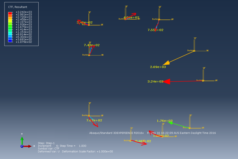
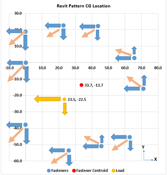
So!! After doing this, running my FEM, I extract my CTF forces, using the probe function, to conduct a quick input/'sum of x&y' forces check and came within 2%. However, I find that my resulting forces are in odd directions when compared with a classical bolt analysis check. I thought this may be because of my wire-feature CSYS, however upon changing the direction of my wire feature for these ones, the same thing occurs, with my forces being in odd directions.
I have attached two images, one of the FEM force directions (excuse my terrible arrows) and the other of my classical analysis (much better arrows).


Any advice would be greately appreciated!! Thanks in advance.
Cheers,
Jakob
I have a scenario where I have a Bracket in an aircraft mounting to an airframe using rivets. I have 10 fastener holes with 3 of those piggy backing onto existing aircraft rivet locations, so in those three locations I am riveting through 3 'plates'.
My model is solid elements with frictionless contacts. I have used the following process of creating a reference point in the centre outside face of the hole, with a coupling constraint to the hole surface. I then created a wire feature between my RP's on opposite ends of the hole and set up my Connector Assignments to the wire-set.
So the idea is that I want to simulate the stresses in the Bracket for its design taking the stiffness of the airframe into account and drawing my stresses out of FE. However, this is not the case for the fasteners, as I want to draw my CTF forces out and analyse in-plane shear, axial, bearing stresses using classical techniques.
So!! After doing this, running my FEM, I extract my CTF forces, using the probe function, to conduct a quick input/'sum of x&y' forces check and came within 2%. However, I find that my resulting forces are in odd directions when compared with a classical bolt analysis check. I thought this may be because of my wire-feature CSYS, however upon changing the direction of my wire feature for these ones, the same thing occurs, with my forces being in odd directions.
I have attached two images, one of the FEM force directions (excuse my terrible arrows) and the other of my classical analysis (much better arrows).


Any advice would be greately appreciated!! Thanks in advance.
Cheers,
Jakob
