Continue to Site

Eng-Tips is the largest engineering community on the Internet

Intelligent Work Forums for Engineering Professionals

  • Congratulations GregLocock on being selected by the Eng-Tips community for having the most helpful posts in the forums last week. Way to Go!

Cutting section of structural column cap plate 1

Status
Not open for further replies.

N3M4N

Structural
Aug 15, 2018
24
Hi All,

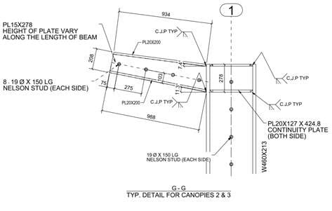
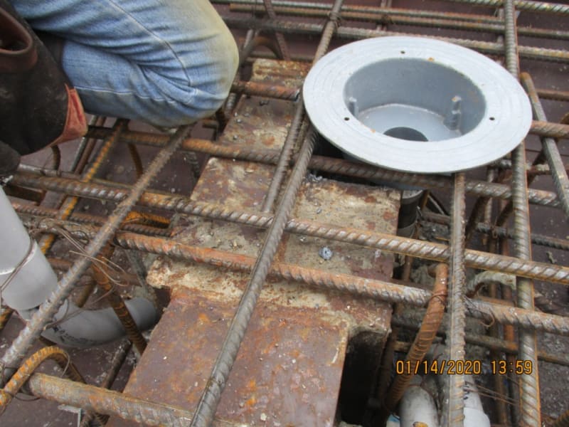
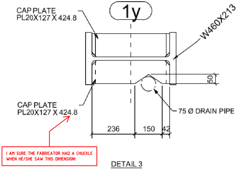
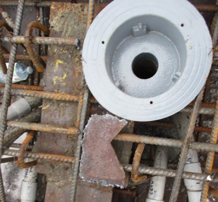
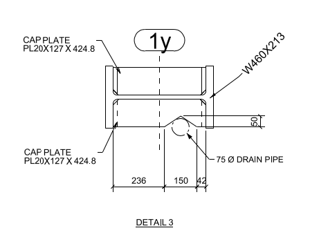
I am looking for your thoughts on the attached pictures, approx 4” x 8” steel column cap plate was cut to accommodate installation of canopy roof drain. what is the significance of the cap plate? Do you see any structural problem with cutting a section out. Thanks.
IMG_2813_hpy3ok.jpg


Steel_column_detail_.jpg_gaznnx.png


Steel_column_xuyrap.jpg
 
Replies continue below

Recommended for you

This is a shear transfer plate (tension stiffener), that works together with the wide flange column, through shear transfer to the column web, to develop moment strength required for the cantilever beam. By cutting it, the stress path is interrupted, and the capacity is compromised.

[EDIT]Is the cut close to the cantilever beam, or at the other end? If it is the latter case, you can do a quick check to see whether a full length stiffener plate is required.
 
Is the cut close to the cantilever beam, or at the other end?
Thanks for your response, the cut section is at the other end.
IMG_2812_a3aogu.jpg
 
Are you the engineer? Or are you the contractor? I feel like the engineer that designed the building would be the correct guy to ask.

It looks like that hot rolled steel is fairly old to be just having the slab poured, is this a modification to an existing structure?

It also looks like they likely have cut the matching hole in the lower plate, that hole would be more concerning to me then the one in the upper plate.
 
So, you can, or someone else can, perform a calculation on the canopy to find the strength demand, and check the required length of the stiffener plate. I believe there are examples on AISC connection design manual that you can follow.

Since this is a canopy, wind load will control the design, you can find information from ASCE7 on wind pressure, and methods to apply the load. Note that although I call the plate a tension stiffener, the force can reverse to compression, as the canopy could be pushed downward, or lifted upward by wind force. Therefore, your plate need to satisfy both tension and compression requirements. Hope this helps.

 
Evaluate the load on the beam and check if complete removal of one side over that length works.

The detail doesn't say what the weld is between the stiffener and the column web, the orginal designer may have used the full length for example to transfer the shear to the panel Zone in sizing the weld. Though it could have just been a CJP as they seem to use them everywhere even if not needed (like the far side stiffener to column flange weld being CJP for no real reason).

Did the same removal of the stiffener occur at the bottom flange level as well?

In terms of any remedial action, even though they cut out a massive chunk of plate, the second photo seems to show some gap between the fitting and the column web where some area replacement plate could be reinstated. Though with the limited access for welding and inspection it might be a waste of time as it needs to be connected adequately to the remains of the plate, this may mean some welding from the underside which looks like it has its challenges. But your best bet is to try satisfy yourself whether a fix is required. I bet in hindsight moving the drain over a few inches would have minimal impact...


Hope you picked up on the fact they also appear to have cut the bar going over the column cap plate.
 
No, the bottom cap plate is intact.

yes additional reinforcement will be provided.

 
All, thanks for your feedback this was helpful.
 
N3M4N:
The ‘remedial action’ should be that we get to use the same implements to remove their nuts as they used to mess up our structure, be it a cutting torch, a saw or drill, a jack hammer, whatever. And, there ought to be a law which allows this. They ought to be trained to realize that our sole purpose in life isn’t to put ugly stuff in the way of their beautiful work, our stuff may actually have a real purpose. And, you should certainly back charge them for this training and your effort. You do still have a fairly generous triangular stiffener (length of stiffener), which goes from the col. flg. to the col. web, to get that load back into the col. web.
 
Definitely check with the engineer of record but I'd say that this is likely fine given that most engineers would be fine with the arrangement shown below in most cases.

I take it slab shear is transmitted to the steel frame vial the nelson studs and/or bearing on the beam bottom flange and low stiffeners?

c01_wm1hov.jpg
 
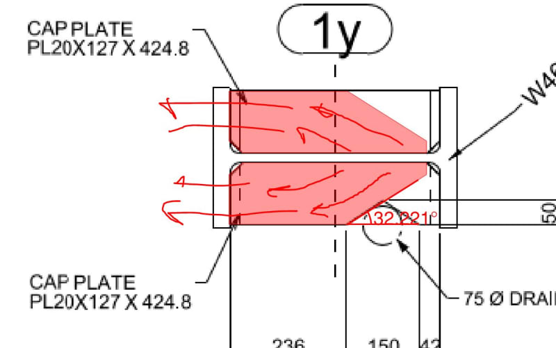
Koot, that plate lying around in the photos is what they cut out, see the nice vee cutout from the drawing on the bit removed. What was provided originally is what you've drawn your nice loadpaths on. But reality looks like roughly half the stiffener depth was removed right up to the Column Web.

Provided the reduced length stiffener worked in shear and tension over the shorter length, and the weld was also sufficient over the reduced length then following a, similar logic to which you've sketched I'm sure someone could show it worked in tension/compression.
 
I see what you mean Agent. Much more cringe worthy. Thanks for setting me straight.
 
Looked up the dims on that column. She's a beast. 60 mm across the web fillets and 33 mm flanges. 60 + 2 x 2.5 x 33 = 225. An inch wider than the incoming plate. I'd be surprised if the stiffeners were needed at all. That said, the design is the design and the responsible engineer may have been contemplating "other stuff" like fatigue, joint stiffness, torsional column stability, etc.
 
Also if the column stiffeners played any part in supporting the slab it might be worth discussing with the original engineer to discount this. Last thing you want to do is impact on the gravity support for the slab. I'm imagining the column is concrete encased and provides the support for the slab since there are studs going down the column.
 
Move the drain and restore the cap plate. It's just a little plumbing.
 
Status
Not open for further replies.

Part and Inventory Search

Sponsor