Continue to Site

Eng-Tips is the largest engineering community on the Internet

Intelligent Work Forums for Engineering Professionals

  • Congratulations KootK on being selected by the Eng-Tips community for having the most helpful posts in the forums last week. Way to Go!

Cylindricity of Component

Status
Not open for further replies.

umatrix

Mechanical
Jul 18, 2013
62
Hi All,

Conceptually, I understand, but not sure how to apply to check to see if my part is in spec. Individual measurements are falling out of the range provided, but the averages meet the print.


I have a bushing, on the part the tolerance is given as
70.1 mm
69.9 mm
GD&T is given here
min_mac_cz0yqc.jpg


Measurements taken from part
min_max_hfv8hg.jpg


How does this cylindricity of 0.7 relate to the tolerance of 70.1 and 69.9 on the print? Do my values fall within this range?

Thank you.
 
Replies continue below

Recommended for you

Are you using the Independency symbol or maybe the part is subject to free state variation (using the F symbol)? Are you using AVG symbol?

If not then why cylindricity is not refinament of size ? 0.7 cylindricity versus 0.2 size.

 
Right -- according to the ASME Y14.5 rules, the size callout alone (69.9 to 70.1) is automatically supposed to provide a form control (unless the "independency" idea is invoked, or other exceptions that Kedu noted). If you have access to that Y14.5 document, you can look for what they call Rule #1 Limits of Size or the Envelope Principle.
 
Hi Kedu,

I am relatively new to GD&T.. It is my understanding of cylindricity is that the radial distance between the two cylinders is the value of the cylindricity control tolerance.

So for my example the tolerance on the part is given 70.1 and 69.9 which is 70.1-69.9 = 0.2 then radius of that would be 0.1 ( I want to confirm I have this understood correctly ?)


However specified on the part for cylindricity is 0.7 which I don't understand.
 
Can we see the notes on the drawing and also the notations to the right of the position callout?
 
So for my example the tolerance on the part is given 70.1 and 69.9 which is 70.1-69.9 = 0.2 then radius of that would be 0.1
No... the diametrical difference of 0.2 does allow the cylindricity error to be 0.2 (even though a cylindricity tolerance is indeed a radial separation, in this case of 0.2).

I know that sounds contradictory, but the reason is that -- without a GD&T callout for cylindricity -- the size tolerance alone allows the form error of 0.2 to appear as a single bump/lobe all on one side.
Attached is a graphic that has a different example but you can see how the form error is biased to one side. So the diametrical error equates with what circularity or cylindricity perceives as a radial error.
 
 https://files.engineering.com/getfile.aspx?folder=4c3d97c1-69a2-46e2-b02b-6215e9edda4e&file=CircularityError.pdf
Belanger, I like it. I fear that I may not know what I am asking, or asking it correctly.


Screenshot_2021-02-23_140505_b1w6fi.jpg


From a GD&T beginners perspective, how do I interpret this drawing?

what is the cylindricity of part, tolerance numerically the print list 0.7, but can I calculate/ confirm that from the tolerance 70.1 and 69.9 ?


How would I use that information in reference to determining if the measurements are within spec. (Someone measured part with caliper and provided these results below)

min_max_hn3qxa.jpg


OD of 70.35 is out of spec, larger that 70.1.

Thanks
 
Cylindricity covers the relationship of each surface element to all others on the toleranced surface. It cannot be verified with a caliper. It is a difficult tolerance to verify, often using a CMM and complex software from the CMM maker.

In any case it's an FCF callout, not a GD&T callout.
 
Thanks 3DDave. So this part would be out of spec because the OD max 70.55 is larger that the specified 70.1 ?


Hi Kedu,
Nobody knows.. I asked the CAD dept, they do not know. lol.
 
umatrix said:
Nobody knows.. I asked the CAD dept, they do not know. lol.

Maybe....just maybe.....Note 1 it is something to get rid of rule#1........
 
Agree with Kedu.

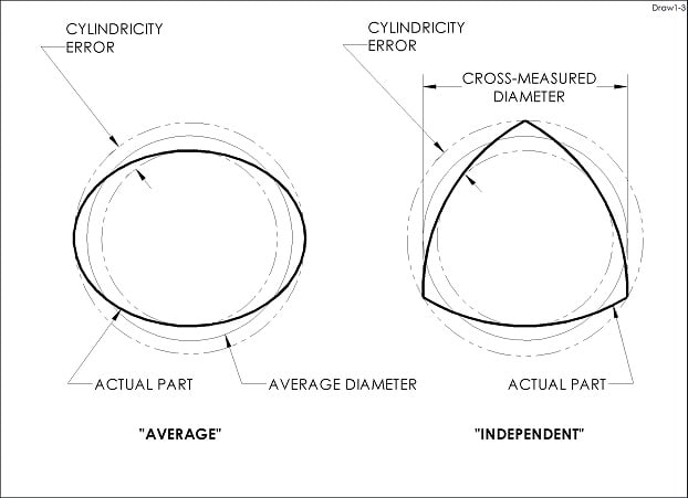
Average or Independence ... and sky is the limit:

Draw1_yjfvuo.jpg


"For every expert there is an equal and opposite expert"
Arthur C. Clarke Profiles of the future
 
Kedu -- if it were to nullify Rule 1 then it wouldn't make sense to also flag the position callout with the same note.
 
Belanger said:
Kedu -- if it were to nullify Rule 1 then it wouldn't make sense to also flag the position callout with the same note.
Agree.
 

Turns out the damm part is oval. I learned a lot from our discussion, thank you everyone.
 
It strikes me odd that "average" was used in the standard instead of circumference, a simpler and more direct indication of the typical interface requirement for easily/elastically deformable items. Cylindricity of the free state would govern how much force would be required to push the part to fit the nominal mating part. It would also be nice to have a curvature control for local deformations, which would also cover flatness (curvature of zero).
 
Hi Kedu, yes, you were right there is an AVG callout next to the symbols.

According to ASME Y14.5 2018
8.5 Average Diameter
"An average diameter is the average of several diametric measurements across a circular or cylindrical feature. The individual measurements may violate the limits of size, but the average value shall be within the limits of size.Typically, an average diameter is specified for parts that are flexible in a non restrained condition."

That explains why the individual measurements exceed the tolerance 70.1, but the averages are within the size.
Screen_Shot_2021-02-23_at_11.14.46_PM_nnupuo.png


I have to study ASME Y14.5 more, very informative.

Thank you everyone.

umatrix
 
Status
Not open for further replies.

Part and Inventory Search

Sponsor