Continue to Site

Eng-Tips is the largest engineering community on the Internet

Intelligent Work Forums for Engineering Professionals

  • Congratulations waross on being selected by the Eng-Tips community for having the most helpful posts in the forums last week. Way to Go!

Dallas Texas Crane Collapse (Wind) 2

Status
Not open for further replies.
Replies continue below

Recommended for you

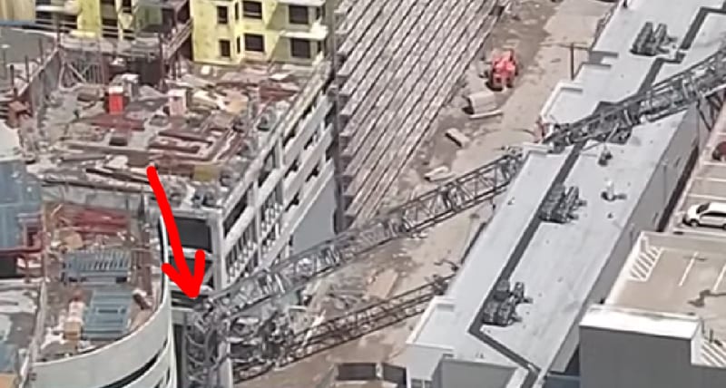
Windstorm - from this snippet - maybe just too much wind drag on the crane and a member failure near the bottom:
Dallas_Crane_rsv8tc.jpg


Check out Eng-Tips Forum's Policies here:
faq731-376
 
Don't say wind until you know it wasn't something else.
 
The video of the actual collapse was during a severe wind event in Dallas.
Here's a drone shot of the parking garage portion - looks like a multi-story pancake collapse:
dallas_crane_2_bu8cro.jpg


Check out Eng-Tips Forum's Policies here:
faq731-376
 
This seems to be getting more frequent.

Could they put these cranes into a more tolerant configuration? Perhaps hook them to something rigid and put a small load on them so they aren't free to sway and perhaps get out of their vertical survival envelopes?

Keith Cress
kcress -
 
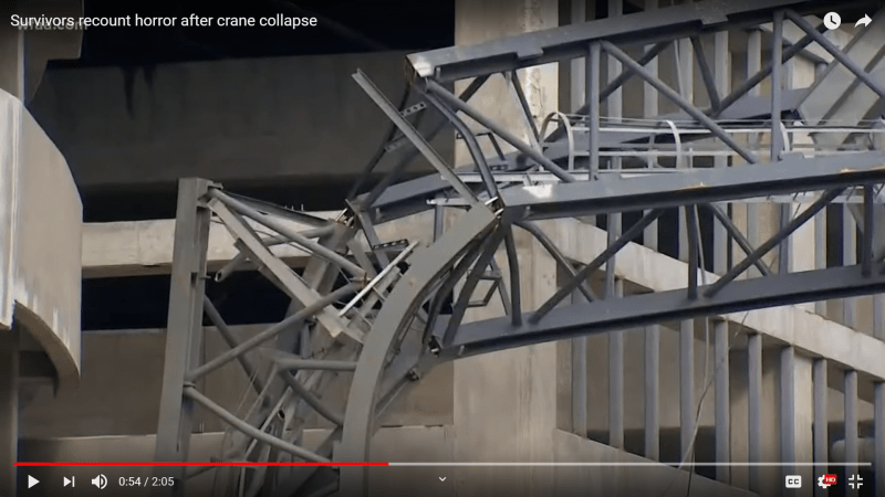
Section fasteners failed due to overload force from wind gust? I hope they don't find fasteners were missing, wrong grade, or counterfeit.

2019-06-09_1_git04r.png
 
Possibly the correct fasteners were improperly torqued.

Bill
--------------------
"Why not the best?"
Jimmy Carter
 
What wind speed are these supposed to be designed for? I presume they are considered "temporary" structures.

 
jrs 87- That picture looks strange. It almost looks like a CG graphic, but I assume it's a picture. I think the 'section fasteners' are the long silvery pins exposed between the crane verticals, missing from the members that parted. If so, then I do not understand how they work unless they were left untightened by a foot or so as they span a large gap between the surviving connections. I would expect that they are either through bolts or pins with some type of associated hardware to provide the proper tension. Is there something else going on at this connection? Also, the crane that fell in Seattle a couple of weeks ago looks like these connections were made by cross-bolting together interlocking sections, instead of the surface to surface connections shown here.

Brad Waybright

It's all okay as long as it's okay.
 
Yeah - this tower section construction/connection appears completely different than the Seattle crane. Seattle crane used HSS members at the corners and this one used what appear to be WF. The Seattle crane used some sort of an insert inside the HSS with pins connecting between the insert and the exterior HSS. Pins appeared to be in shear only there.

Here, it seems that the connectors are in tension.

This *could* be the crane. (no evidence other that it looks like it) [URL unfurl="true"]https://www.bigge.com/crane-information/peiner-sk575/[/url]

Anyone know what the 'tie-bars' mentioned in the text below the video in that link are?

(Same as my comments in the last crane thread - I don't know anything about tower cranes but am genuinely curious)
 
I don't see any distortion of the steel at the left-front leg connection in the video frame posted by @jrs_87. This basically suggests that the bolts/rods never existed. I suppose there is a circumstance where the bolts could rupture in tension as the initial point of failure, but then why can we see the shanks of all the other bolts/rods?
 
One possibility- the bolts on that one leg failed, the others didn't fail. When the bolts on that leg failed, the leg was still straight enough they could just drop out (more like, got shot out, I guess). The other bolts were twisted around with the structure but didn't fail.
If that was my crane, I'd sure be looking for those broken bolts.
 
JStpehen, I agree - the initial failure would be pure tension in the bolts; either they parted, lost their heads, or shed the nuts. In any case the leg with the initial failure would be straight. It's all the other ones that would be distorted.
 
azcats (Structural)10 Jun 19 15:29

azcats said:
Anyone know what the 'tie-bars' mentioned in the text below the video in that link are?

The best information I have is that tie-bars attach tower to nearby finished section of structure.
 
Ok, so tower cranes are designed with two criteria --

They're designed for a certain in-service load criteria. Say a 30-40mph wind simultaneous with loads on the hook, slewing around, etc. This is a "temporary structure" kind of design.

They're also designed for out-of-service loads, entirely from environmental conditions (primarily wind). (No allowance for operational loads, since the crane is to be shut down if a major storm approaches). In this configuration, they are designed as essentially permanent structures, or at least with a long enough mean recurrence interval to stand up to all except the most extreme storms. There's a procedure to follow when a storm approaches -- usually bringing in the trolley/hook and allowing the jib to slew freely ("weathervane").

As such, I'm sure that the crane manufacturer designed the crane itself to resist a storm of this magnitude. They would have provided reactions for the tie-backs (if used) and foundations to use when designing those elements.

So a few possible causes of failure, in no particular order:
[ul]
[li]Storm procedures weren't followed correctly[/li]
[li]Tie-backs were required for that configuration, but not installed[/li]
[li]Tie-back anchorages weren't designed properly[/li]
[li]Connections weren't made correctly during crane erection (as speculated above)[/li]
[li]Material failure in the connections (as speculated above)[/li]
[/ul]


----
just call me Lo.
 
Is it possible for the winds to shift faster than the jib can weathervane?
 
In a tower like this, and almost any structure really, the primary system would have been designed first, indifferent of the connections. The connections would have been designed second, and in some cases by a delegated designer. The main directive of connection design is to ensure that the primary structure reaches capacity, and fails the way the primary system was designed, and not to introduce any new global failure mechanisms. For the bolted connection to fail in pure tension before the other legs failed in buckling would raise flags about the original designs (or material or installation of course).

But if the bolts/rods were properly installed and if they failed in pure tension, then I wonder that I can see no evidence of related distortion in the plate steel around the 4 connections. Just eyeballing it I'm guessing those are 1" bolts with 5/8 plate steel. How do 4 bolts rupture without any flares or dimples or tears in the plate?

Hopefully more information will turn up.

 
Status
Not open for further replies.

Part and Inventory Search

Sponsor