Continue to Site

Eng-Tips is the largest engineering community on the Internet

Intelligent Work Forums for Engineering Professionals

  • Congratulations KootK on being selected by the Eng-Tips community for having the most helpful posts in the forums last week. Way to Go!

Datum feature symbol attached to a callout common to hole and c'bore/sink 1

Status
Not open for further replies.

Burunduk

Mechanical
May 2, 2019
2,358
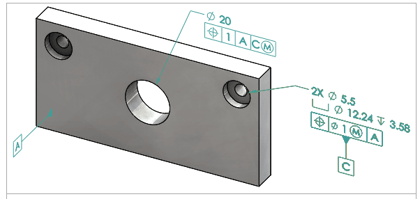
When a datum feature symbol is attached to a callout common to both the hole+counterbore or a pattern of them as in This example or to a hole+countersink or a pattern of them as in this example, is there any rule in ASME Y14.5 or related standards that tells clearly that the datum feature is understood to be the hole(s) and not the counterbore/sink(s)?
Or maybe it's vise-versa?
Or maybe it should be understood that both features/patterns act as a "common datum feature" (of hole+c'bore/sink, repeated in pattern if applicable)? Are those placements of the datum feature symbol unambiguous? I tried to find something about it in Y14.5 with no success, but maybe I'm missing something?

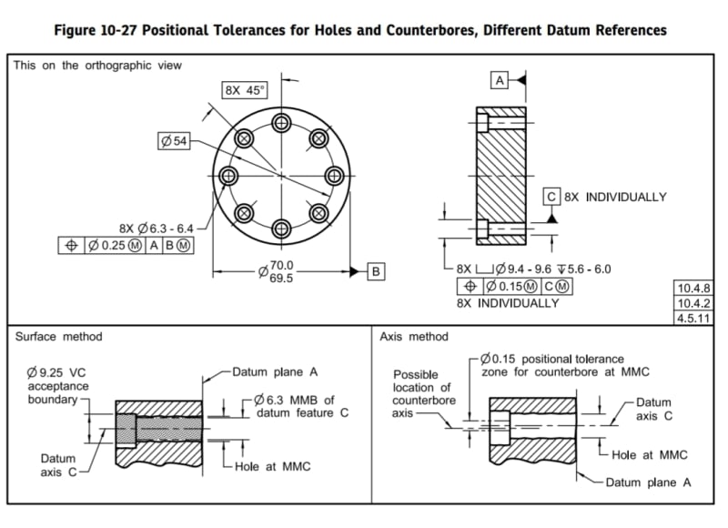
Both examples are from here.
 
Replies continue below

Recommended for you

For some unknown reason (at least to me), Y14.5 does not provide a clear answer to this question.

My opinion, based on the rule for applicability of a single FCF in the hole-counterbore case, has always been that the datum feature symbol attached this way defines both features - the hole and counterbore/countersink - as datum features, which in many (most?) cases makes no functional sense. Therefore, I would avoid using this method of datum feature assignment in such instances.

Unfortunately, I have seen GD&T materials available for free in the internet these days (which are very popular) that seem to care very little about it and keep showing examples like the ones you brought up without any caution remark.
 
pmarc,
I don't understand the lack of coverage, either.
Could the lack of a rule or standardized convention for these cases simply be an oversight? Do you think it could be that the possibility of placing a datum feature symbol on such FCF never crossed the committee members' minds?
The examples are actually from SolidWorks MBD help page, I think it's even worse than if it was from some questionable free "GD&T" training source.
 
I don't think this never crossed the committee members' minds. I lean towards saying that they don't see a problem with it, i.e., that in their minds the standard provides all necessary information to be able to clearly interpret the datum feature placement method.
 
Burunduk

Thanks for the patterned datum link, that's a very useful reference.
But I have a question on the second picture (Two concentric hole pattern used as secondary datum), there is no intersection point between the primary datum feature A and the axis of the two hole pattern, where is the datum point on this |A|B|C| DRF?

Or anything I missed. Thanks for your help.

Season
 
SeasonLee,
This is how the [A,B,C] datum reference frame is established for the second image example in the SolidWorks link I posted in the opening post:

The primary planar datum feature A provides a datum plane - the first plane of the DRF.
The secondary datum feature, the pattern of two coaxial holes, provides a datum axis. From ASME Y14.5, we know that "Depending on the number of planes established by higher-precedence datums, secondary and tertiary datum axes may establish zero, one, or two theoretical planes" (7.10.3 Parts With Cylindrical Datum Features). The "theoretical planes" mentioned are planes of the DRF.
So, since one plane is already established from datum A, the datum B axis (which is parallel to A) establishes one plane, the second DRF plane. That second DRF plane coincides with the 'B' axis, and is perpendicular to datum plane A. Finally, datum C is the third plane of the DRF, perpendicular to the first two.
Let me know whether this makes sense.
 
I know there is an intersection point between the two hole pattern and tertiary, I haven't seen an example with no intersection line or point from the primary datum and sceondary datum feature. That's my question.

Season
 
pmarc said:
I lean towards saying that they don't see a problem with it, i.e., that in their minds the standard provides all necessary information to be able to clearly interpret the datum feature placement method.

But they are wrong, aren't they?
Even with the common callout,
the cylindrical holes and the countersinks or counterbores are still two different patterns of two different features (even if not entirely separate, since a simultaneous requirement makes the two patterns become part of one pattern, that includes both the cylindrical holes and the countersinks or counterbores).
In the examples I brought, does the common callout imply that the 'B' datum is established based on two datum axes, each of which is common to the cylindrical hole and its respective counterbore/sink per the "common datum features" concept? I don't see anything in the standard that may clearly indicate that.
 
SeasonLee said:
I haven't seen an example with no intersection line or point from the primary datum and sceondary datum feature.

There is no problem with that.
There will be an intersection between the primary datum plane and a theoretical plane which the secondary datum axis is associated with / related to.
 
Burunduk said:
In the examples I brought, does the common callout imply that the 'B' datum is established based on two datum axes, each of which is common to the cylindrical hole and its respective counterbore/sink per the "common datum features" concept? I don't see anything in the standard that may clearly indicate that.

However, the standard provides examples based on which one can probably easily come up with a solution for a situation where the intent is that the holes and counterbores/sinks ARE NOT common datum features, doesn't it?

Using the counterbore example,...
-- if the intent is to define the 2 holes only or 2 the c'bores only as datum features, then separate the c'bore size callout from the hole size callout, associate each of the size callouts with a positional FCFs of the same value and then apply the datum feature A symbol to just one of them. This would be a variation of the approach shown in fig. 10-26 in Y14.5-2018.
-- if the intent is to define only a single hole or counterbore as datum feature, then keep the size+position FCF callout as is but associate the datum feature A symbol with that specific single feature only. This could be a variation of the datum feature C specification from fig. 10-27 (just with the omission of the 8X INDIVIDUALLY note) or the application of the technique shown in fig. 6-4(i).

Am I just playing a devil's advocate here? ;-)
 
pmarc,
Are you saying that it is possible to prove by contradiction that the axes used for the datum construction are of common datum features uniting the hole+c'bore/sink? It may be so, but it is not a trivial conclusion, at least for me.
Initially I was thinking the most probable answer to what the datum should be derived of in such cases are the holes, simply because they are much more common as datum features. C'bores and especially c'sinks are rarely used as datum features, from various reasons.
Speaking of which, considering how a countersink is usually dimensioned and toleranced, its true geometric counterpart determination may be problematic and even ambiguous. Do you see what I mean?
 
Hi,

I don't like saying right or wrong, just typical and atypical. It is my understanding that the datum feature simulator in those cases would be a combination of the clearence hole and the counterbore together. It would be atypical to use a counterbore as a datum.

Personnaly, in such case, I would create a section view of the hole and dimension the counterbores seperatly from the clearence holes. I would then use the clearence hole as datum. If possible, I would use a profile of a surface to locate and dimension the counterbore. if not, I'd locate the counterbore to the hole individually.

Does that make sense?
 
Burunduk,
I am just saying that one (for example the committee member) could use this type of argumentation to prove that the standard covers the topic in sufficient detail.

The c'sink example is problematic not only due to the "what is datum feature for this combined callout" dilemma. It is not even clear if the position tolerance is applicable to the c'sink and if it is, to what element it applies.

Regardless of the example, I don't think I would use the commonness argument in the conversation. Different things are common to different people.
 
pmarc,
I understand and agree.
The point about counterbore/sink features not being common as datum features was only to explain why my initial instinct was that only the holes are the datum features. Not intended as an argument for the correctness of such interpretation.

I would say that the position tolerance being of questionable applicability to a countersink is not the last problem on the list. There is also what I was hinting at - unless the included angle of the countersink is specified as basic (which is atypical) or undimensioned and defined by the CAD model provided as the basic geometry, the true geometric counterpart for countersink is not well-defined, at least in my opinion. Would you agree?
 
supergee said:
Personnaly, in such case, I would create a section view of the hole and dimension the counterbores seperatly from the clearence holes. I would then use the clearence hole as datum. If possible, I would use a profile of a surface to locate and dimension the counterbore.

Just curious, not that it's wrong, but why profile of a surface and not a directly toleranced diameter dimension and a position tolerance for the counterbore?

supergee said:
if not, I'd locate the counterbore to the hole individually.

Wouldn't it be "individually" in the first case too? Or did you mean in the first case that the holes are position-toleranced with ref. to A and used as a pattern datum feature B, and the counterbores are also position-toletanced as a pattern to A, and therefore in a simultaneous requirement with the holes?
 
Hello Burunduk,

Burunduk said:
Just curious, not that it's wrong, but why profile of a surface and not a directly toleranced diameter dimension and a position tolerance for the counterbore?
As I said, if possible. I don't know the actual use of that counterbore. I teach my students that tolerance of form is magical because it controls form and position. I doubt that there is a fit requirement on the counterbore diameter itself. since ASME says it's trying to move away from direct tolerancing to geomtric tolerancing I tend to use profile of a surface when ever possible. But it can be replaced with a ± tolerance + location. rule #1 will control the form.

Burunduk said:
Wouldn't it be "individually" in the first case too? Or did you mean in the first case that the holes are position-toleranced with ref. to A and used as a pattern datum feature B, and the counterbores are also position-toletanced as a pattern to A, and therefore in a simultaneous requirement with the holes?
In the image shown, the datum is applied to the feature control frame that relates to two holes (2X). This implies that both counterbored holes, together, form the datum. I propose that we separate the counterbore callout from the clearance hole dimensions. This means that we need to ask ourselves if we want to locate the patern of counterbores (PLTZ) with regards to the the true location of the the clearence hole or if we want to locate each individual counterbore with it's own clearence hole. I believe that the second option is the one we typically would like to do.

I am reading this answer over and over. As english is my 3rd langage I am not sure if what I say is clear. I hope it makes sense.

gee
 
supergee said:
I am reading this answer over and over. As english is my 3rd langage I am not sure if what I say is clear. I hope it makes sense.

Your answer is very clear and makes perfect sense regarding the point you are addressing. But, it seems like my question was not very clear. I do understand the difference between the original scheme and using the concept of "INDIVIDUALLY". What was not clear to me is the difference between your first and second suggestions.

Your first suggestion was this:
"Personnaly, in such case, I would create a section view of the hole and dimension the counterbores seperatly from the clearence holes. I would then use the clearence hole as datum. If possible, I would use a profile of a surface to locate and dimension the counterbore."

Since you said you would use the clearance holes as datum features, I assumed you would also control the counterbores relative to them individually. This would be done with a "2X INDIVIDUALLY" indication both near the datum feature symbol which labels the clearance holes as datum features, and near the feature control frame of the surface profile tolerance which applies to the counterbores. Similar example (only with position and not profile for the c'bores, but same idea) is shown in figure 10-27 of ASME Y14.5-2018:
Screenshot_20230420_193320_Drive_pkexlv.jpg


The second suggestion was this:
"if not, I'd locate the counterbore to the hole individually."

This confused me because I thought INDIVIDUALLY was the original suggestion in the first place. So if the first suggestion was something different from what I described and from the method shown in 10-27, what was it?
 
Hello Burunduk,

I had forgotten about that example in the standard, and it is exactly what I had in mind. the difference is that the image shown initially the datum C is establish on both hole as show in the picture below. so datum C is not on one hole but on the pattern of the two holes. in figure 10-27 of y14, it would be equivalent to locating the bore with datum A|B(M) which makes not a lot of sense
Annotation_2023-04-20_124724_yqzc5n.png
 
Supergee,
Thanks for another good explanation of the difference between controlling the counterbores with reference to the clearance holes individually and the method shown in the link I provided.

But actually, I'm looking forward to understanding the difference between your two different suggestions. Again, here are the two suggestions you provided:

1."Personnaly, in such case, I would create a section view of the hole and dimension the counterbores seperatly from the clearence holes. I would then use the clearence hole as datum. If possible, I would use a profile of a surface to locate and dimension the counterbore."

2."if not, I'd locate the counterbore to the hole individually."

Could you please clarify what is the difference between the above #1 and #2?

Thank you.
 
Status
Not open for further replies.

Part and Inventory Search

Sponsor