elinah34,
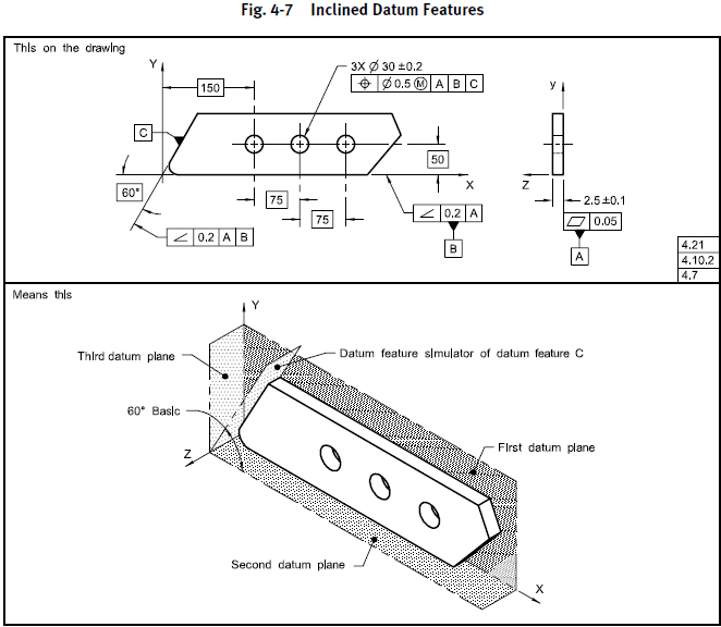
Further to what greenimi said, there can be 3 planar datum features that are not perpendicular to each other. Fig. 4-7 in 2009 (7-13 in 2018) is the only example in Y14.5 that illustrates this (that I can think of):
This figure shows that it is possible to specify planar non-orthogonal datum features and extract a Datum Reference Frame (Cartesian coordinate system). However, there are several misleading things in this example that have made it difficult to generalize to other cases (I have seen a lot of questions about this topic over the years).
The text in 7.10.2 states:
"For parts with inclined datum features as shown in Fig. 7-13, a true geometric counterpart plane is oriented at the basic angle of the datum feature. The corresponding plane of the datum reference frame passes through the vertex of the basic angle and is mutually perpendicular to the other two planes."
These statements are generally correct, but I would make the following comments:
-In this case with relatively simple part geometry, it is possible to make the plane of the datum reference frame pass through the vertex of the basic angle. In other cases, this will not be generally possible.
-This example also uses explicit datum reference frame identification (the drawing has explicit labels for the X, Y and Z axes). This technique is defined in Y14.5 and is a very good practice, but most drawings do not include these explicit labels.
-There is no particular procedure for defining a Cartesian coordinate system in three non-perpendicular planes. In other words, the origin and axis directions of the coordinate system are not uniquely defined if the explicit labels are not used.
Then there is the issue of the terminology that applies to the planes in the "means this" figure. This is where things get really confusing. The text in 7.10.2 uses the correct term "plane of the datum reference frame", but the figure uses the term "datum plane". Using these terms loosely has resulted in a lot of confusion - here's why:
-Each planar datum feature reference invokes a True Geometric Counterpart (TGC) that is a perfect plane at the basic angle of the datum feature
-A datum is extracted from each TGC. For planar datum features, the datum is a plane that is coincident with the TGC. So each planar datum feature reference invokes a datum plane that is at the basic angle of the datum feature.
-A Datum Reference Frame (three-plane Cartesian coordinate system) can be defined in the set of datums. Strictly speaking, these three planes are "planes of the datum reference frame" and not "datum planes".
Planar datum features, particularly when they are are orthogonal to each other, can be confusing because several of the different planes are coincident. So we have to be very fastidious with the terminology. Here are some comments on the planes shown in Fig. 7-13:
-The plane labeled "First datum plane" is:
1. The true geometric counterpart of primary datum feature A
2. Datum Plane A
3. One plane of the datum reference frame (the XY plane)
-The plane labeled "Second datum plane" is:
1. The true geometric counterpart of secondary datum feature B
2. Datum Plane B
3. One plane of the datum reference frame (the XZ plane)
-The plane labeled "True geometric counterpart of datum feature C" is:
1. The true geometric counterpart of tertiary datum feature C
2. Datum Plane C
The plane labeled "Third datum plane" is:
1. One plane of the datum reference frame (the YZ plane)
It is much easier to see the distinction between true geometric counterparts, datums, and planes of the datum reference frame in other examples that include datum features of size. Figure 7-5 is a good one - the datum features are a planar surface, cylindrical hole, and parallel-plane slot.
Evan Janeshewski
Axymetrix Quality Engineering Inc.