Eng-Tips is the largest engineering community on the Internet

Intelligent Work Forums for Engineering Professionals

datum? i am unsure 1

Status
Not open for further replies.

FrancoisY

Mechanical
Nov 10, 2023
13
0
0
US
Hello,

I was wondering what this symbol represents marked in yellow. can someone help me understand the correct terminology for it?
Datumn_ybkeuo.png
 
Replies continue below

Recommended for you

This is from a very early edition of Y14.5 and is a datum feature symbol.

When was the drawing made? I'm expecting it was done before 1970.

Edit: That would be ANSI Y14.5, before ASME took it over. Note the order of the elements in the feature control frame with the datum reference before the tolerance.
 
Could the "DIA" text following the tolerance value instead of the diameter symbol before it also be attributed to the old age of the drawing?
 
This callout would comply with MIL-STD-8C that was taken over as ASA Y14.5-1965 "Dimensioning and Tolerancing for Engineering Drawings" as a Joint Industry-Military Standard. (JIMS)

See "A Treatise on Geometric & Positional Dimensioning & Tolerancing" by Honeywell Regulator Company, authored by Lowell W. Foster, Senior Standardization Engineer at Honeywell Inc. 1963 and revised through 1965.

IMG_4015_oyb57l.jpg
 
SeasonLee, 3DDave, thank you both for the references to past standards.

3DDave, I see that JIMS was referred to as "proposed". Was there eventually a document titled ASA Y14.5-1965 released?
In the sources I read there was ASA Y14.5-1957 and then the next "Y14.5" mentioned is USASI Y14.5-1966. Could the 1965 ASA document be a reaffirmation of the 1957 edition or something? EDIT: I guess not, because it seems that the 1957 standard was based on literal notes such as "LOCATED AT TRUE POSITION WITHIN..." and possibly had no feature control frames or symbols for the geometric characteristics at all.
 
I cannot confirm documents I don't have and/or have never seen. It is probable that the 1965 and 1966 are the same document, moved from ASA to USASI the way that Y14.5 was moved from ANSI to ASME; USASI stands for United States of America Standards Institute (now ANSI) No one appears to have released the 1965 version which Foster was working on releasing under the old group name.

per
ASA_saz206.png


See by DAVID H. HONSINGER for more information.

The 1957 version might as well not exist. Since you know it was notes based you must have a source.
 
My source for information on ASA Y14.5-1957 is Technical Drawing by Frederick E. Giesecke, 4th Edition, 1958.

This is how some of the geometric tolerances (which were all called "tolerances of form" at that time, seemingly) are presented in that book, with an identification of the source being ASA Y14.5-1957:

Screenshot_20240712_113448_Drive_sy7tsr.jpg


Also worth noting that according to the same source, the title of the 1957 standard was "Dimensioning and Notes"

Screenshot_20240712_115205_Drive_qwouxf.jpg
 
Ah, you apparently have the PDF copy, probably from
Print copies appear to be available from:
$15 $11 $20 $14 $24 (shipped from UK to US)

At Worldcat listing 180 across many US public libraries At Internet Archive (same scan as pdfcoffee has.)


Always happy to share.

Many of the controls did have symbols associated with them, but without a copy of the 1957 version (none of this matters in the slightest) it doesn't matter.

I do like what appears to be the origin story for "Geometric Tolerances"

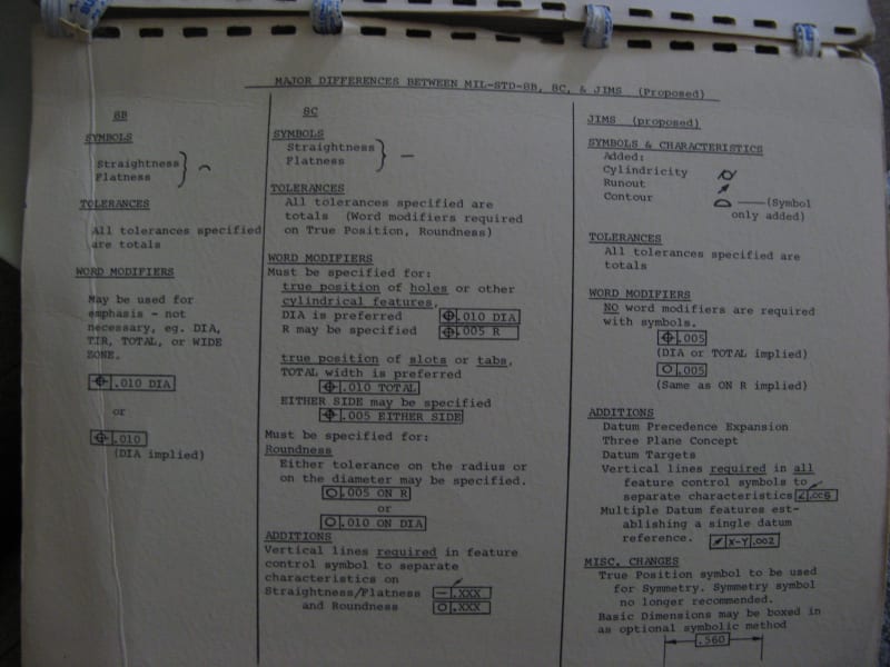
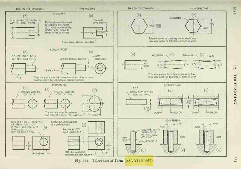
Geometric Tolerances. Geometric tolerance, or "tolerance of form" specifies "how far actual surfaces are permitted to vary from the perfect geometry implied by drawings."* The term "geometric" refers to the various geometric forms, as a plane, a cylinder, a cone, a square, or a hexagon. Theoretically these are perfect forms, but since it is impossible to produce perfect forms, it may be necessary to specify the amount of variation permitted. Geometric tolerances define conditions of straightness, flatness, parallelism, squareness, angularity, symmetry, concentricity, and roundness.
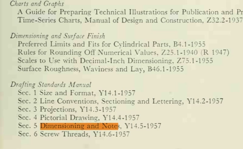
*ASA Y14.5-1957.

They did not include Position tolerance. Makes the whole GD&T term seem even more inaccurate.

Note too the recommendation:

Since it is very expensive to maintain accurate geometric tolerances in the shop, tolerances of form should not be specified except when established shop procedures cannot be depended upon to produce the necessary accuracy.
 
Nice.
Maybe you could also trace where a copy of ASA Y14.5-1957 can be obtained from, and then we could check if it had symbols for the controls or just notes.
I have no proof, but I think "Dimensioning and Notes" was all about dimensions and notes.
 
Thanks pmarc.
Then it appears that the military standards (MIL-STD-8...) had geometric characteristic symbols before the general industry standard (... Y14.5) incorporated such symbols (and the military standards were incorporated into USASI Y14.5-1966).
 
Status
Not open for further replies.
Back
Top