Eng-Tips is the largest engineering community on the Internet

Intelligent Work Forums for Engineering Professionals

Datum line that is not a straight axis 3

Status
Not open for further replies.

Burunduk

Mechanical
May 2, 2019
2,335
0
0
IL
The two most recent versions ('09 and '18) of ASME Y14.5 define a 'datum' as:

Y14.5 said:
datum: a theoretically exact point, axis, line, plane, or combination thereof derived from the true geometric counterpart.
With "line" mentioned as a separate kind.
In past discussions such as thread1103-452649 no clear conclusion was reached about what can be the intent behind the addition of "line" to the definition in the '09 edition of the standard.

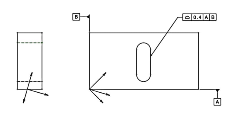
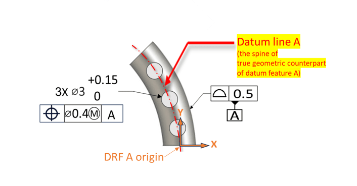
Please see the following diagram.
Do you think, based on the Y14.5 standard, that the shown curved line could be a valid datum corresponding specifically to the "line" type (and only) in the above definition? If not, why?

datum_spine-line_zaeyq6.png
 
Replies continue below

Recommended for you

Burunduk,
I agree the center point of the torus is the most natural choice for the location of the DRF and CSYS origin. Would it fundamentally be a problem if the origin wasn't located at that center point? Again, I am not sure.

By looking at fig. 7-53 in Y14.5-2018, would you say that passing the XY plane of the DRF only through only one of three datum targets A or showing the location of the XZ plane in the top view the way it's been shown and not forcing it to pass through at least one of two datum targets B is a problem?
 
pmarc,
I used to think the exact same thing - that any "natural" DRF placement and orientation can be relocated and re-oriented without consequences as long as the alternative placement establishes a constant and exact spatial relationship with the TGCs.
However, now I have my doubts.
I think it's fairly easy when you have 6 degrees of freedom locked, as in the 7-53 example you brought up. However, when not all DOF are constrained, the DRF placement might become meaningful for analysis.

Look at the following example - the usual thing to do would be to establish one plane of the DRF coincident with datum plane A. It would be clear that 5 DOF are constrained, one translation is not, and datum feature plus the TGC for A constrained 2 rotations and one translation. Assuming the axes of the DRF do represent directions of DOF*, would the above be also clear if the DRF was established at an inclined orientation as shown? I think it would appear that all 6 DOF are constrained, and they all were constrained by A.

*Or should I abandon this assumption??

inclined_drf_f8qh3v.jpg
 
Burunduk,
In my mind the number of constrained DOFs depends on the type of interaction between the datum features and their TGC, and not on how a CSYS is shown on the drawing.

Not to mention (which I am actually doing), that I can envision a situation where there are multiple CSYS but only one DRF on the drawing.
 
pmarc,
But I'm not talking about just any CSYS, I'm talking specifically about the DRF. And it's all about how it's established for tolerance evaluations - as I mentioned, it could have not been shown on the drawing at all (and it probably wouldn't for a simple case like that).

pmarc said:
In my mind the number of constrained DOFs depends on the type of interaction between the datum features and their TGC

So maybe DRF establishment must match that as well? That would mean for a planar primary datum feature such as A in my last example that a plane of the DRF must be coincident with datum plane A. So some of the arbitrariness goes away already. Note that there would still be some freedom to place the DRF origin anywhere along the width of the part (as seen on the left view), since there is no constraint in that direction. And once it can't be completely arbitrary, the torus problem could be resolved too by requiring the DRF origin to align with the center point of the torus. What am I missing?
 
Burunduk,
If the DRF/CSYS is not shown on the drawing, then why is having a default location and orientation of the DRF/CSYS so important to you? Please take a look at fig. 7-57 in Y14.5-2018. In that figure, they show a DRF and CSYS, however the XZ plane of the DRF does not even pass through the axis of the datum feature C TGC, which shouldn't be the case per what you are saying. Knowing how the pattern of 3 holes is nominally oriented and located on the part relative to datum features B and C , I kind of understand why they did it that way and I am not sure I would like to force anyone to visualize the DRF in one and only one way.
 
pmarc said:
If the DRF/CSYS is not shown on the drawing, then why is having a default location and orientation of the DRF/CSYS so important to you?
So that it will be possible to consistently describe the degrees of freedom being constrained or unconstrained by the axes of the DRF (even if its CSYS is not shown on the drawing). I don't like to think of the inclined DRF from my last sketch as a legitimate DRF while the linear movement in all 3 directions represented by its axes, and the rotational movement about them, is stopped by the planar TGC for datum feature A. That in my opinion creates two problems:
1. A planar primary TGC should constrain only one translation and only two rotations. Not 3 translations, and definitely not all 6 degrees of freedom.
2. If we accept that a primary planar TGC does constrain only 3 degrees of freedom (as always), and yet, that the shown inclined DRF is still valid, we must also accept that the axes of the DRF do NOT represent the degrees of freedom (constrained or not) of the part under the application of the datum references for the given geometric tolerance. I think that would not be corresponding to the standard.
As for 7-57, there are 2 things to note:
1. Datum C is not primary.
2. TGC of datum feature C can constrain rotation about the center axis of the TGC of datum feature B with the DRF as shown. So the plane not passing through datum axis C does not reduce from the clarity of how the degrees of freedom work in this case.
 
1. A planar TGC interacting with a planar primary datum feature always constrains 3 DOFs.

2. If the relationship between the CSYS and datum features in your last example is considered basic (in a case where the CSYS is not shown on the drawing) or defined basic (in a case where the CSYS is shown on the drawing), then it should be quite easy to figure out the axes that "constrain" the degrees of freedom, if someone needs to know them.
 
pmarc,
I am not sure what you mean by "figure out the axes that "constrain" the degrees of freedom".
Do you agree that once datum feature A and its planar TGC are mated, movement along any of the shown axes is not possible and neither rotation about those axes?
 
pmarc, I'm trying really hard to make sense of it. I agree, too, that "it does not mean the TGC constrains 6 degrees of freedom" - it definitely constrains only 3, unlike what could mistakenly be concluded from the unfeasibility of movement in these specific directions.
So are you saying that despite that, this CSYS could theoretically be a representation of a valid (even if not "natural") DRF?
If you don't see a fundamental problem with the alternation of the DRF from the "natural" default to an arbitrarily displaced/rotated (in this case - rotated) position, should I conclude that you consider, as I put it earlier - "that the axes of the DRF do NOT"-(necessarily)-"represent the degrees of freedom (constrained or not) of the part under the application of the datum references for the given geometric tolerance"? In other words - is this the idea; there is the DRF CSYS that could be directed however one likes, and there are, as a potentially different CSYS without a unique name, the directions of the applicable constrained (and unconstrained) degrees of freedom. ONLY the latter CSYS (and not the DRF) always depends on the geometry of the TGCs and their precedence order - such as a translational constraint direction normal to a primary planar TGC, or a rotational direction specifically about the central axis of a primary torus-shaped TGC.
Am I on the right track of interpreting what you are saying?
 
I am just saying the CSYS does not have to be aligned with the "natural" DRF, because it does not have to represent the DRF.

 
I never cared about any CSYS that does not represent a DRF.
So what about the DRF?
Does this eventually mean that the DRF does have to be established at a "natural" location and orientation relative to the TGCs and can't be just anywhere one likes and/or oriented totally arbitrarily, even if basic/theoretically exact dimensional relationships are kept with the TGCs? The caveat would be that sometimes there can be a variety of such appropriate establishment positions, but often not.
Again, I'm not talking about placement of just any CSYS for dimensioning on the drawing. I'm talking specifically about the DRF as defined (and not necessarily shown on the drawing).
 
Status
Not open for further replies.
Back
Top