Continue to Site

Eng-Tips is the largest engineering community on the Internet

Intelligent Work Forums for Engineering Professionals

  • Congratulations KootK on being selected by the Eng-Tips community for having the most helpful posts in the forums last week. Way to Go!

Datum line that is not a straight axis 3

Status
Not open for further replies.

Burunduk

Mechanical
May 2, 2019
2,358
The two most recent versions ('09 and '18) of ASME Y14.5 define a 'datum' as:

Y14.5 said:
datum: a theoretically exact point, axis, line, plane, or combination thereof derived from the true geometric counterpart.
With "line" mentioned as a separate kind.
In past discussions such as thread1103-452649 no clear conclusion was reached about what can be the intent behind the addition of "line" to the definition in the '09 edition of the standard.

Please see the following diagram.
Do you think, based on the Y14.5 standard, that the shown curved line could be a valid datum corresponding specifically to the "line" type (and only) in the above definition? If not, why?
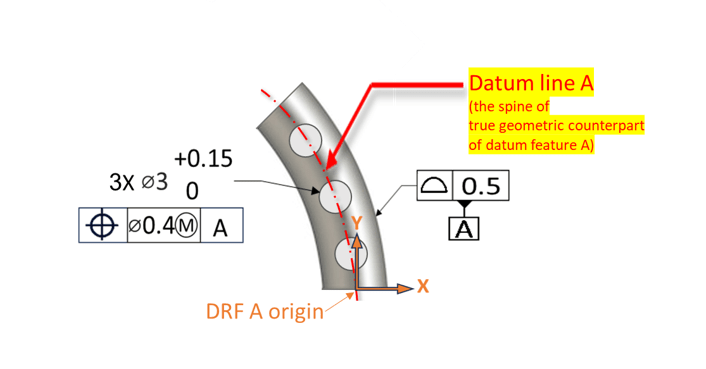
datum_spine-line_zaeyq6.png
 
Replies continue below

Recommended for you

So why the situation feature has been introduced in ISO? What is its purpose?
Is it more like a "general term" that groups together other ISO terms (like planes,lines, points) ?
Is there an equivalent in ASME of this name "situation feature"?
Looks like you clarified that TGC in ASME is the "associated feature" in ISO GPS therefore maybe "situation feature" is more general term for the "associated feature"

Could someone clarify my confusion, please?
I am afraid I am more confused about ISO terms than ASME ones😜🤣
 
Kedu,

For an on-line peek:

Per ISO 22432:2011(en), Geometrical product specifications (GPS) — Features utilized in specification and verification
---
3.2.5.1.2
situation feature
geometrical feature defining the location or orientation of an ideal feature and which is a geometrical attribute of the ideal feature
See Figures 4 to 7.

Figure 4 — Example of situation planes
Figure 5 — Example of situation lines
Figure 7 — Example of situation helix
---

Corresponds to ASME Y14.5-2018, Figure 7-3 Constrained Degrees of Freedom for Primary Datum Features, which skips the helix.

---

For a torus, ISO specifies the situation feature is "Plane and centre of the associated torus (plane and point)" from Table A.2 — Default association criteria for a feature which is not a feature of size or for a feature of size with fixed intrinsic characteristics, BS EN ISO 5459:2011/ISO 5459:2011(E)

---

Why the name? Because "situation" is defined as "the position of something" and "the particular position of a building, business, city, etc.:", from latin "situs";
Why the concept? It is from an analysis of constraints.

ISO is better thought out and they also present better examples. Y14.5 may seem less complicated due to the simplistic example and less rigorous vocabulary.
 
Kedu,
At least in the context of datums, situation features are just the theoretical elements such as the points, lines, planes - that either constitute a datum or are part of the datum. In ASME, these are just points, lines, planes. No need for another term to introduce confusion. It is not an "associated feature". An "associated feature" would be the circumscribed perfect cylinder for a pin, the situation feature would be its axis.

The abundance of terms and rules that apply to special cases is the reason they have a separate standard for datums, and separate standards for many topics covered in the ASME world by just Y14.5. So potentially there is much more to sell to the users (they also update standards more frequently), and it's the ideal hotbed for training material providers. However, my personal impression is that ISO users generally tend to pay much less attention to "GPS" and rarely use the entire set of standards or get reasonably familiar with all of them. ASME users seem to care about "GD&T" and apply it much more.
 
Burunduk said:
Here's another observation which I wonder what you think about:
Usually one can relocate the datum reference frame from any default location to any arbitrary place which may be found convenient, as long as the relationship between the DRF axes and the true geometric counterparts that interact with the datum features is theoretically exact and constant (do you disagree?). I think the default for a torus-shaped primary datum feature would be to establish the DRF origin coincident with the axis of the TGC of the feature (that axis would be directed into/out the page, located a radius away to the left of the part). In that case it's clear that a rotational DOF about that axis remains. However if for convenience I translate the DRF to where it is currently shown in my figure (to bring it closer to the part) it is no longer clear which DOF remain free and which are constrained. Relative to the currently shown CSYS, the tangential transformation looks like a translation in a non-constant direction, and it doesn't look like any rotational DOF is unconstrained. It means that at least in this particular case the DRF has a meaningful placement that shouldn't be overridden. What would you say?

This could actually be an argument for situation features.

The main use case for labelling DOFs on drawings made in accordance with Y14.5 is when the customization of a DRF happens. In such cases it does indeed matter where the CSYS is shown on the drawing. However, in ISO the customization is done differently, by explicit cancellation of default situation features of the datum feature(s) referenced in the geometric tolerance indicator, and so the CSYS may still be anywhere one wants as long as it stays basically related to the situation feature(s) that has/have left.
 
3DDave said:
3.2.5.1.2
situation feature
geometrical feature defining the location or orientation of an ideal feature and which is a geometrical attribute of the ideal feature
See Figures 4 to 7.


Interesting synopsis.
I am wondering what is the difference between TEF and situation feature in this context.

From ISO1101:2017
"theoretically exact feature
TEF
nominal feature with ideal shape, size, orientation and location, as applicable
Note 1 to entry: A theoretically exact feature (TEF) can have any shape and can be defined by explicitly indicated theoretically exact dimensions (TEDs) or implicitly defined in CAD data.
Note 2 to entry: The theoretically exact location and orientation, if applicable, is relative to the indicated datum system for the specification of the corresponding actual feature.
Note 3 to entry: See also ISO 25378.
EXAMPLE 1:The spherical surface shown in Figure 110 is a theoretically exact feature, with a defined spherical radius and a defined location and orientation relative to datum A.
EXAMPLE 2:A virtual condition, e.g. a maximum material virtual condition (MMVC) according to ISO 2692 is a theoretically exact feature."


I think with soooooo many ISO terms I am lost too :)

I am trying to compare

"situation feature
geometrical feature defining the location or orientation of an ideal feature and which is a geometrical attribute of the ideal feature"


WITH

TEF "The theoretically exact location and orientation, if applicable, is relative to the indicated datum system for the specification of the corresponding actual feature"


TEF appears to fill the function of the nominal feature or related actual mating envelope, hence "Note 2 to entry: The theoretically exact location and orientation, if applicable, is relative to the indicated datum system for the specification of the corresponding actual feature."

situation feature = the location portion of a TEF.

For a sphere in 3D: <X, Y, Z, R (or D)> is the TEF and <X, Y, Z> is the point situation feature of the sphere.

 
greenimi,
Here is the problem that possibly got you confused about the difference between TEF and situation feature: while in ASME a "feature" is a physical portion of the part, in ISO everything is a feature.
ISO's "situation feature" is not really a feature in Y14.5 terms, but it is a theoretical element such as a point, line, or plane. A theoretically exact feature on the other hand is true profile in ASME - it is what you aim the toleranced feature to be, as defined by basic dimensions (TEDs).
 
pmarc said:
The main use case for labelling DOFs on drawings made in accordance with Y14.5 is when the customization of a DRF happens. In such cases it does indeed matter where the CSYS is shown on the drawing.
What if I don't want to show the DRF CSYS on the drawing. I could want to only interpret it as a 3 planes and 3 axes set located wherever I want (fixed relative to the TGCs) and establish it that way in practice, as a measurement reference. But that is not really possible without losing the clarity of the constraints, is it?
 
Burunduk,
If you don't show the DRF CSYS, then all you can unambigously do is talk in terms of the number and types (rotational vs. translational) of DOFs constrained by each TGC. But you cannot precisely label/name the DOFs like x, y, z, u, v, w.
 
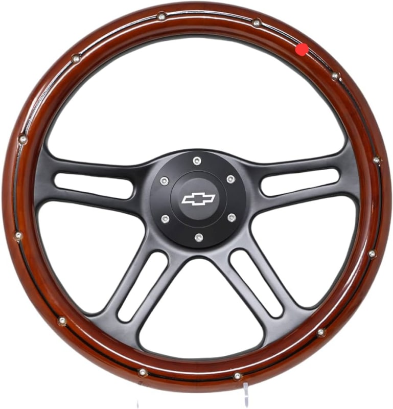
pmrac, but in this case, to unambiguously tell that a torus shaped feature's TGC leaves one rotation unconstrained, I still have to assume the that the free rotation's axis is the axis of the torus shaped TGC, and acknowledge that it is also an axis of the DRF (no matter whether it's labeled x, y or z). If I want to place the DRF origin arbitrarily, such as on the spine of the torus, considering an unconstrained rotational DOF would be like trying to rotate a wheel about the red point.

61l8XTnOVpL._AC_UF894_1000_QL80__getk9o.jpg


Since you can't do that, it already sets the DRF at a specific location that can't be altered (except along the axis). That is what I've been saying. Maybe then it isn't true that the DRF can always be established anywhere as long as its location and orientation is constant relative to the TGCs?
 
Burunduk,
I am not sure I see a huge problem with placing the CSYS at the red point as long as one does not start to customize the DRF per Y14.5 rules.

But at the same time I think I like where you are going with "[...] it already sets the DRF at a specific location that can't be altered (except along the axis)" (except that I would say that in this particular example the only acceptable alteration should be rotation of the DRF about the "center point" of the torus in the plane of the screen). I am just afraid the problem with this way of looking at the location of the DRF origin is that for a complex datum feature, such as a feature similar to the irregular feature shown in fig. 11-24 in Y14.5-2018, it may not be clear where the point of the plane+line+point datum system should be exactly located.
 
Guys,

I kind of know, in ASME, that the CSYS could be placed anywhere as long as it is basic from the applicable features.

ASME 14.5-2018
So, it is no surprise that in fig 7-13 the CSYS is where it is (outside of the angled part), but I think could be anywhere (really anywhere) as long as the basic dimensions are adjusted (basic linear dimensions, basic angles).
Now, on fig 7-29, probably it is the same idea, but what I am not understanding is where 16.7 basic dimension is coming from? Is this dimension just a random location for the CSYS?
If not then what it is?

pmarc said:
.....placing the CSYS at the red point as long as one does not start to customize the DRF per Y14.5 rules.......

Why does not? Why the customization will have this restriction of CSYS not being able to be placed anywhere?

And my last question: how ISO GPS solve this issue or in general terms, could you place the coordinate system anywhere in ISO? I haven't seen (x, y, z, u, v, w's) in ISO.


Fig. 7-13 has the CSYS exactly aligned to the DRF.

Fig. 7-29 - clearly explained as the origin of the mathematical definition of the part, so it is not random.
 
3DDave said:
Fig. 7-13 has the CSYS exactly aligned to the DRF.

Fig. 7-29 - clearly explained as the origin of the mathematical definition of the part, so it is not random.

So, in fig 7-29 is the CSYS aligned to the DRF too? If yes, then is there ANY figure in Y14.5 where CSYS is NOT aligned to the DRF?

 
greenimi said:
is there ANY figure in Y14.5 where CSYS is NOT aligned to the DRF?
Wherever a CSYS is shown in the standard's figures, it always represents the DRF.
 
Burunduk,
Thank you for clarification "Wherever a CSYS is shown in the standard's figures, it always represents the DRF"

So, why you want the CSYS not be aligned with the DRF? Do you know any cases where this approach (not alignment) is preferable?

pmarc said:
Regarding location of the origin of the coordinate system, again all different options are possible and allowed. In such cases I like to say that the origin of the CSYS could even be located on the Moon provided that there is a basic location relationship between the Moon and the used datum feature simulators. But will this add any value to a part like a flat plate with 5 thru holes in it? Most likely not, and that's why the most natural and straightforward choice is to place the origin of the CSYS at the center of the feature that per the design intent is responsible for location of the part in an assembly. If someone decides to show the origin at a different place (such as one of the centers of the 4 smaller holes in the considered plate), it is his/her choice, but the risk may be that this will cause a confusion to the readers of the drawing. And for sure this will not change the way the part gets constrained relative to the datum feature simulators, because this is something that is encoded in the datum portion of the feature control frame and not in how a CSYS is shown on the drawing

Burunduk said:
Since you can't do that, it already sets the DRF at a specific location that can't be altered (except along the axis). That is what I've been saying. Maybe then it isn't true that the DRF can always be established anywhere as long as its location and orientation is constant relative to the TGCs

My follow up question is: why CSYS cannot be altered?
For sure I am the one which is missing some knowledge here.
Could someone clarify my doubts, please?

 
pmarc said:
I am not sure I see a huge problem with placing the CSYS at the red point as long as one does not start to customize the DRF per Y14.5 rules.

greenimi said:
My follow up question is: why CSYS cannot be altered?

Evan said:
In other words, the placement of the "datum planes" and DRF origin are completely arbitrary. The only thing that really matters is the mutual relationship between the datum feature simulators.

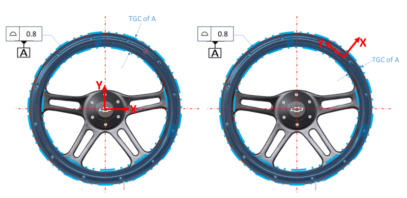
In the following image, in both cases the primary datum feature is a torus. The TGC of datum feature A envelopes the actual torus and immobilizes the part somewhat. On the left side the DRF is established at the center of the torus which would probably be considered the most natural placement for it. In this case it's quite clear that 5 degrees of freedom - 3 translations and two rotations are constrained, and one rotation is unconstrained. The rotation which is unconstrained is about the torus' center axis (w). On the right side the DRF is established on the central spine of the torus shaped TGC. The ZX plane is coincident with the torus axis so it's not even "completely arbitrary". Is it clear in this case which DOF are constrained and unconstrained, and are they the same as in the first case? I would say not quite, and no. u,v,w rotations seem to be constrained and so is the z translation. x and y - they are kind of constrained because you can't move the part straight and directly in either of these directions, but also kind of unconstrained since the tangential (to the spine) transformation is possible, which has components of x and y, but the direction is not constant around the torus. In short - the result of not placing the DRF in the center results in unclear situations.
drf_placement_uxqnae.png
 
Burunduk,
In the picture on the right you get into the trouble because you want to give names (such as u, v, w, x, y, z) to the DOFs based on the CSYS shown. I agree that placing the CSYS on the spine isn't natural and may lead to confusion, therefore most people, including me, don't generally do it that way. However, this, in my opinion, should not mean the CSYS cannot be put elsewhere or be oriented at any other arbitrary angle, as its orientation and location have generally no effect on the number and type of DOFs constrained by the toroidal TGC. In other words, regardless of where you put the CSYS, 5 DOFs (3 translations and 2 rotations) have been constrained - no more, no less. Also, if the datum feature was a complex geometry (much more irregular in shape than the beautifully symmetrical "complex" feature shown in fig. 7-3(g)), based on what criteria would you recommend defining the default location and orientation of the CSYS?
 
pmarc,
I agree about "truly" complex datum features, such as Tandler's "Point-on-Line-in-Plane" datum type. There is no way to tell where the point and line must be if they must be in only one location (and orientation for the line) relative to the datum feature and the TGC.
However, with the torus, I'm still not certain more than one DRF location makes sense. If we want it to be clear that "5 DOFs (3 translations and 2 rotations) have been constrained - no more, no less" as you say, and someone can't see what the unconstrained rotation is about, don't we want to point to the center of the torus and say - "the part can rotate about this axis"? If yes, isn't it where an axis of the DRF should be located? Note that I'm not giving that rotation a specific name - could be u, v, or w - doesn't matter. I'm used to thinking that the DRF axes define the directions of the degrees of freedom that are considered as part of the constraints applied by datum references. Is there any other way to look at it? I can't see how a rotational DOF is available about an axis located anywhere but at the center of the torus. Do you see it differently?
 
Status
Not open for further replies.

Part and Inventory Search

Sponsor